
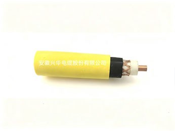
I. ProductPurpose and Features
RF Coaxial Cable for Coal MineMainly Used Forleaky communication systems, wireless video surveillance systems, etc.; it is a critical infrastructure ensuring unimpeded wireless communication in mines. By providing stable, low-loss high-frequency signal transmission channels while ensuring flame-retardant, explosion-proof and other safety characteristics, it enables reliable mobile communication, personnel positioning, and wireless monitoring in complex underground environments, and is an indispensable component of modern intelligent and safe mining.
II.Product Standards
MT/T 386-2011
III. Product NameandModel
Model No. | Name Description | Main Application Scope |
MSYV-75-(3 、4 、5 、7 、9 、12) | RF Coaxial Cable for Coal Mine | Used for mine radio communication and personnel positioning systems |
MSYV-50-(3 、5 、7 、9 、12) | RF Coaxial Cable for Coal Mine | Used for mine radio communication and personnel positioning systems |
IV.Product Specifications
Model No. | Inner Conductor (Body) | Insulation (Insulation) |
Outer Conductor Single Wire Diameter | Outer Sheath Thickness (Thickness) |
Cable (Cable) Outer Diameter | |||
Number of Wires/Diameter Diameter | (Diameter) Nominal | Outer Diameter Minimum |
Outer Diameter |
(Diameter) |
Outer Diameter | |||
MSYV-50-3 | 1/0.90 | 0.90 | 0.85 | 2.95±0.13 | 0.13~0.15 | 0.75 | 0.58 | 5.0±0.2 |
MSYV-50-5 | 1/ 1.40 | 1.40 | 1.30 | 4.80±0.20 | 0.13~0.15 | 0.88 | 0.69 | 7.2±0.3 |
MSYV-50-7 | 7/0.75 | 2.25 | 2.00 | 7.25±0.25 | 0.18~0.20 | 1.05 | 0.85 | 10.3±0.3 |
MSYV-50-9 | 7/0.95 | 2.85 | 2.60 | 9.00±0.30 | 0.18~0.20 | 1.18 | 0.96 | 12.2±0.4 |
MSYV-50-12 | 7/ 1.15 | 3.45 | 3.50 | 11.5±0.30 | 0.18~0.20 | 1.30 | 1.00 | 15.0±0.4 |
MSYV-75-3 | 7/0.17 | 0.51 | 1.05 | 3.00±0.13 | 0.13~0.15 | 0.66 | 0.45 | 5.0±0.2 |
MSYV-75-4 | 1/0.59 | 0.59 | 1.25 | 3.70±0.13 | 0.13~0.15 | 0.80 | 0.60 | 6.0±0.2 |
MSYV-75-5 | 1/0.75 | 0.75 | 1.60 | 4.80±0.20 | 0.13~0.15 | 0.88 | 0.69 | 7.2±0.3 |
MSYV-75-7 | 1/ 1.15 | 1.15 | 2.77 | 7.25±0.25 | 0.18~0.20 | 1.05 | 0.85 | 10.3±0.3 |
MSYV-75-9 | 1/ 1.37 | 1.37 | 3.20 | 9.00±0.30 | 0.18~0.20 | 1.18 | 0.96 | 12.2±0.4 |
MSYV-75-12 | 7/0.63 | 1.89 | 3.80 | 11.5±0.30 | 0.18~0.20 | 1.30 | 1.00 | 15.0±0.4 |
Thickness
5.1 V. Technical Requirements
Inner ConductorGB/T395.1.1 The inner conductor material of the cable shall comply with
the requirements for soft round copper wire specified in 53, and the structure of the inner conductor shall comply with Table 2. 5.2 5.1.2 The conductor surface shall be smooth, free of oil stains, burrs that may damage the insulation, sharp edges, and protruding or broken single wires.
Insulation
The insulation shall use polyethylene insulation material, and its performance shall comply withYDthe requirements of /T760.
5.2.2 Insulation Structure
The insulation shall be tightly extruded onto the conductor, shall be easily strippable without damaging the insulation, the surface shall be smooth, uniformly colored, and shall be free of cracks and other defects.
The minimum insulation thickness and outer diameter shall comply with Table 2, and the eccentricity shall not exceed 10%. The insulation eccentricity shall be tested in accordance withIEC61196-1-302:2008 .
5.3 Outer Conductor
5.3.1 Outer Conductor Material
The outer conductor material of the cable shall comply with the soft round copper wire requirements specified in Table 2.
5.3.2 Outer Conductor Structure
The outer conductor structure shall comply with Table 2, and the braiding angle shall not exceed 45 °,The braiding density shall not be less than 90%.
During outer conductor braiding, single-direction missed braiding of one spindle is allowed, and the missed braiding length shallnot exceed 100mm, and the splice points shall be trimmed neatly.
5.4 Outer Sheath
5.4.1 Outer Sheath Material
The outer sheath color shall be blue (or a color as required by the customer)),The material shall use flame-retardant polyvinyl chloride cable material, and its performance shall comply withGB/T the requirements of 8815.
5.4.2 Outer Sheath Structure
The outer sheath surface shall be smooth, free of visible pinholes, cracks, bubbles, and other defects,and slight braiding patterns are allowed. The nominal thickness and minimum thickness of the outer sheath shall comply with Table 2, and the cable outer diameter shall comply with Table 2.
5.4.3 Outer Sheath Mechanical Properties
The mechanical properties of the outer sheath shall meet the requirements of Table4
Table 4 Outer Sheath Mechanical Property Requirements
No. No. |
Item (Item) |
Unit | Indicator (Indicator) |
Flame-Retardant PVC Sheath | |||
1 | Tensile Strength Before Thermal Aging Treatment (Minimum Value) Change Rate Before and After Thermal Aging |TS|(Maximum Value) Thermal Aging Treatment Temperature Thermal Aging Treatment Time | MPa % | 12.5 25 |
℃ h | 100±2 168 | ||
2 | Elongation at Break Before Thermal Aging Treatment (Minimum Value) After Thermal Aging Treatment (Minimum Value) Change Rate Before and After Thermal Aging |EB|(Maximum Value) Thermal Aging Treatment Temperature Thermal Aging Treatment Time | % % % | 150 / 25 |
℃ h | 100±2 168 |
5.5 Electrical Performance
5.5.1 Conductor Continuity
5.5.1.1 The inner and outer conductors of the cable shall be continuous.
5.5.1.2 It canbe verified by applying an appropriate indicator (such as a multimeter, indicator light, or buzzer) to the electricalcable at each conductor or shield layer at both ends with a voltage not exceeding 36V the DC voltage shall be checked. Test voltagecan be applied individually or in series.
5.5.2 Dielectric Withstand Voltage
The cable in accordance withIECthe method specified in IEC 61196-1-105:2005 shall withstand Table 3specified dielectric withstand voltage test, and shall not exhibit breakdown.
5.5.3 Sheath Withstand Voltage
The cable shall undergo the sheath withstand voltage test by one of the following methods and shall not exhibit breakdown. The water immersion test is thearbitration test.
a) The water immersion test specified in Table 5 shall be conducted in accordance with the method specified in IEC 61196-1-106:2008.
b) The spark test specified in Table 5 shall be conducted in accordance with the method specified in IEC 62230:2006.

Table 5 MSYV Series 50Ω 、75Ω Flame-retardant RF Coaxial Cable for Coal Mines — Electrical Performance
Model No. | Dielectric Withstand | 5.1.2 The conductor surface shall be smooth, free of oil stains, burrs that may damage the insulation, sharp edges, and protruding or broken single wires. | Sheath Withstand Voltage | Corona Extinction | Average |
Attenuation Constant 20℃ | 3000MHz | ||
Voltage ( RMS) | Resistance M Ω.km | (RMS)/kV | Voltage ( value)kV | Characteristic Impedance | Attenuation Increment dB/m | ||||
Spark | Water Immersion | Frequency | Attenuation≤ | ||||||
kV | ≥ | Voltage | Voltage | ≥ | Ω | MHz | dB/m | ≤ | |
MSYV-50-3 | 4.0 | 5000 | 3.0 | 2.0 | 2.0 | 50±2 | 200 | 0.220 | 1.50 |
MSYV-50-5 | 6.5 | 10000 | 5.0 | 3.0 | 3.3 | 50±2 | 200 | 0.150 | 1.50 |
MSYV-50-7 | 10.0 | 10000 | 8.0 | 5.0 | 5.0 | 50±2 | 200 | 0.110 | 0.75 |
MSYV-50-9 | 12.0 | 10000 | 8.0 | 5.0 | 6.0 | 50±2 | 200 | 0.095 | 0.75 |
MSYV-50-12 | 15.0 | 10000 | 8.0 | 5.0 | 7.5 | 50±2 | 200 | 0.080 | 0.75 |
MSYV-75-3 | 2.0 | 10000 | 3.0 | 2.0 | 1.5 | 75±3 | 200 | 0.280 | — |
MSYV-75-4 | 4.2 | 10000 | 3.0 | 2.0 | 2.0 | 75±3 | 200 | 0.190 | 1.50 |
MSYV-75-5 | 5.5 | 10000 | 5.0 | 3.0 | 2.7 | 75±3 | 200 | 0.150 | 1.50 |
MSYV-75-7 | 10.0 | 10000 | 8.0 | 5.0 | 5.0 | 75±3 | 200 | 0.120 | 0.75 |
MSYV-75-9 | 10.0 | 10000 | 8.0 | 5.0 | 5.0 | 75±3 | 200 | 0.088 | 0.75 |
MSYV-75-12 | 12.5 | 10000 | 8.0 | 5.0 | 6.0 | 75±3 | 200 | 0.080 | 0.75 |
Note:For attenuation constants at other frequencies, refer to Appendix A of GB/T 14864-2013.。
5.5.4 Insulation Resistance
The cable in accordance withIECMeasured by the method specified in IEC 61196-1-102:2005. The insulation resistance shall comply with the requirements of Table 3. For mass production, factory inspection may use a 500V insulation resistance tester or megohmmeter for testing.
5.5.5 Characteristic Impedance
The cable in accordance withIECMeasured by the method specified in IEC 61196-1-108:2005. The characteristic impedance shall comply with the requirements of Table 3.
5.5.6 Attenuation
The cable in accordance withGBMeasured by the method specified in GB/T 17737.1-2000. The characteristic impedance shall comply with the requirements of Table 3.
5.5.7 Corona Extinction Voltage
The cable in accordance withGBTested by the method specified in Appendix C of GB/T 14864-2013. The corona extinction voltage of the dielectric shall comply with the requirements of Table 3.
5.6 Environmental and Mechanical Performance
5.6.1 Low-Temperature Bending Performance
The cable in accordance withIECAfter the bending performance test in accordance with IEC 61196-1-201:2009, the insulation and sheath surfaces shall be free of visually visible mechanical damage. The test conditions are shown in Table 6. The mandrel diameter shall be 10 times the cable outer diameter.
Table 6 Environmental Test Conditions
Low-Temperature Bending Performance | Heat Flow Resistance of Dielectric | Thermal Shock Resistance | Temperature Cycling | Dimensional Stability | |||||
Temperature ℃ | Duration /h | Temperature ℃ | Load Weight kg | Temperature ℃ | Duration /h | Temperature ℃ | Duration /h | Temperature ℃ | Duration /h |
-15±2 |
22 |
98±2 | 2.5(1.5<D≤5.0) 5(5.0<D≤7.0) 7(7.0<D≤17.8) |
98±2 |
168 | 98±2 15~35 -15±2 | 168 1 20 |
85±2 |
20 |
5.6.2 Heat Flow Resistance of Dielectric (applicable only to cables with nominal insulation diameter greater than 1.5mm and less than 17.8mm the cable)
The cable shall be subjected toGBthe heat flow resistance test of the dielectric specified in Clause 10.6 of GB/T 17737.1-2000, the inner conductor shall not deviate from the cablecenter by more than 15% of the nominal insulation diameter. The test conditions are shown in Table 5.
5.6.3 Thermal Shock Resistance (Winding Test After High Temperature)
The cable shall be subjected toGBAfter the thermal shock test specified in Clause 10.7 of GB/T 17737.1-2000, the insulation and sheath surfaces shall be free of visuallyvisible mechanical damage. The test conditions are shown in Table 5.
5.6.4 Contamination Test After High Temperature
Before and after the cable is subjected to the high-temperature treatment under the thermal shock test conditions in Table 5, in accordance withGBGB/T 17737.1-2000Clause 10.13, measure the attenuation at 20°C. The increment shall comply with the requirements of Table 4.
5.6.5 Temperature Cycling
After the cable undergoes temperature cycling treatment in accordance with the test conditions specified in Table 5, immediately in accordance withIECIEC 61196-1-201:2009, perform the bending performance test. After the test, the insulation and sheath surfaces shall be free of visually visible mechanical damage. The mandrel diameter shall be 10 times the cable outer diameter.
5.6.6 Dimensional Stability (applicable only to cables with insulation outer diameter less than or equal to 7.25mm the cable)
The cable shall be subjected toGBAfter the dimensional stability test specified in Clause 10.9 of GB/T 17737.1-2000, the insulation relative to the inner conductorshall not displace along the cable axial direction by more than 3mm. The test conditions are shown in Table 5.
5.7 Flame Retardant Performance
The flame retardant performance of the cable shall meetMTthe test requirements specified in Clause 4.2 of MT/T 386-2011.
5.8 Length
The delivery length of finished cables shall be as specified in the contract. The measurement tolerance of length shall be ±0.5%, and shall be verified using a length counter.
6 Inspection Rules
6.1 Inspection Classification
Cable inspection is classified into type tests, sample tests, and routine tests.
6.2 Type Test (T)
Type tests shall be conducted under any of the following circumstances:
1) Type approval for trial production of new products or when existing products are transferred to another factory for production;
2) After formal production, if there are significant changes in process, formulation, or structure that may affect productperformance;
3) When renewing the product inspection certificate;
4) When there is a dispute between the supplier and the customer regarding product quality that requires arbitration;
5)When the national quality and technical supervision authority requests inspection.
All cables produced for use in coal mines must undergo type testing by a nationally accredited qualified testing center in accordance with this standard, and obtain “Product Inspection Report ”。
6.3 Sampling Test (S)
6.3.1 Sampling Method
Product batch size less than 5km, sampling shall be no less than 3 sections; if batch size is greater than 5km, every additional 5km, add test specimen1sections.
6.3.2 If any item in the sampling test fails, differentrolls (reels) shall be taken for double the test specimens to re-test the failed item for inspec-tion; if still failing, 100% inspection of the failed item shall be conducted on the batch of cables, and those failing shall be deemed non-conforming products.
6.4 Routine Test (R)
The product shall be inspected and qualified by the manufacturer's quality inspection department and accompanied by a qualityinspection certificate before leaving the factory. The quality inspection certificate shall at least include the following contents:
1) Manufacturer name;
2) Product model and specification;
3) Length (m);
4) Date of manufacture or production batch number;
5) Standard number;
6) Safety (Indicator) Mark (Indicator) ing and its certifi cate num No. ;
7) Quality inspection special seal.
6.5 Finished cables shall be tested in accordance with the table 7 specified tests to verify compliance with the corresponding requirements.
Table 7 Test Methods and Inspection Rules
No. | Item (Item) | Clause No. | Test Type | Test Method |
1 | Conductor Continuity | 5.5.1 | T、R | This Standard |
2 | Dielectric Withstand Voltage | 5.5.2 | T、R | IEC61196-1-105:2005 |
3 | Sheath Withstand Voltage | |||
3.1 | Spark Test | 5.5.3 | R | IEC62230:2006 |
3.2 | Water Immersion Test | 5.5.3 | T | IEC61196-1-106:2008 |
4 | Appearance Inspection | 5.4 | T、R | Visual Inspection |
5 | Marking | 7.1 | T、S | Visual Inspection |
6 | Length | 5.8 | T、S | Length Counter |
7 | Insulation Resistance | 5.5.4 | T、S | IEC61196-1-102:2005 |
8 | Inner Conductor Structure | 5.1 | T、S | GB/T4909.2-2009 |
9 | Insulation Thickness and Diameter | 5.2.2 | T、S | GB/T2951.11-2008 Chapter 8 |
10 | Dielectric Eccentricity | 5.2.2 | T、S | IEC61196-1-302:2008 |
11 | Outer Conductor Braid Density | 5.3.2 | T、S | GB/T17737.1-2013 Medium 3.2 |
12 | Sheath Thickness and Diameter | 5.4.2 | T、S | GB/T2951.11-2008 |
13 | Sheath Mechanical and Physical | 5.4.3 | T | GB/T2951.11-2008 |
14 | Characteristic Impedance | 5.5.5 | T、S | IEC61196-1-108:2005 |
15 | Attenuation Constant | 5.5.6 | T、S | GB/T17737.1-2013 Medium 11.13 |
16 | Corona Extinction Voltage | 5.5.7 | T | GB/T14864-2013 Appendix C |
17 | Low-Temperature Bending Performance | 5.6.1 | T | This Standard 5.6.1 and IEC61196-1-201:2009 |
18 | Heat Flow Resistance of Dielectric 1 | 5.6.2 | T | GB/T17737.1-2013 Medium 10.6 |
19 | Thermal Shock Resistance | 5.6.3 | T | GB/T17737.1-2013 Medium 10.7 |
20 | Contamination Test After High Temperature | 5.6.4 | T | This Standard 5.6.4 |
21 | Temperature Cycling | 5.6.5 | T | This Standard 5.6.5 |
22 | Dimensional Stability 2 | 5.6.6 | T | This Standard 5.6.6 and GB/T17737.1-2013 Medium 10.9 |
23 | Flame Retardant Performance (Single Vertical Burning Te- st) | 5.7 | T、S | MT/T386-2011 Medium 4.2 |
Note:1 Applicable only to cables with nominal insulation diameter greater than1.5 mm and less than 17.8 mm,2Applicable only to cables with insulation outer diameter less than or equal to7.25 mm.
7 Marking
7.1 Product Marking
The product marking shall be printed on the cable sheath surface by embossing or with ink whose color is clearly distinguishable from the sheath color. The product marking shall includethe following contents:
1) Manufacturer name:
2)Cable model and specification;
3) Safety mark identification and its certificate number.
The printing shall be clear and durable, with printing interval not exceeding 1m。
7.2 Packaging Marking
On the exterior of the cable, the manufacturer is permitted to apply other markings, but the use of other markings shall not impair the legibility and clarity of the specified printing.ness. Each roll or reel of cable shall be affixed with a label indicating the following contents:
1) Manufacturer name;
2) Product model and specification;
3) Length (m) and gross weight (kg);
4) Date of manufacture or production batch number;
5) This standard number;
6) Safety mark identification and its certificate number;
8 Packaging, Transportation and Storage
8.1 Packaging
8.1.1 Cables shall be delivered in rolls or on reels, and their ben-ding radius shall not be less than GB/T14864-2013 Appendix A the specified value. Both ends of the cable must be sealed, and rolled (reeled) cables shall be properly packaged.
8.1.2 The weight of roll-packaged cable shall not exceed 50kg。
8.1.3 Reel-packaged cables must be neatly wound onto cable drums. The cable drums shall comply with JB/T8137 requirements. The cable drum shall be marked with the correct rotation direction of the cable drum.
8.1.4 Each roll or reel of cable shall be affixed with a label indicating the marking contents specified in clause 7.2.
8.2 Transportation and Storage
Cables shall be suitable for all modes of transportation by water, land, and air. Special attention:
1) Prevent moisture and humidity from entering the cable;
2) Prevent severe bending and other mechanical damage;
3) Prevent high temperature and exposure to direct sunlight.
If you are interested in our products, or want to ask related questions, please leave a message to us.
We will reply and serve you as soon as possible. Thank you for visiting our official website.