
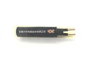
I. ProductApplication and Characteristics
For Coal Mine UseControlControl cables are mainly used for transmitting control electrical energy, driving equipment actions, and transmitting data signals. They are specially designed for harsh underground mine environments.isa special cable for reliably and safely controlling and operating equipment。
II. Product Standards
GB/T 2900.10
III. Product Type Designationand Name
Type Designation | Name |
MKVV | Coal Mine PVC Insulated PVC Sheathed Control Cable |
MKVVP | Coal Mine PVC Insulated PVC Sheathed Braided Shielded Control Cable |
MKVVP2 | Coal Mine PVC Insulated PVC Sheathed Copper Tape Shielded Control Cable |
MKVV22 | Coal Mine PVC Insulated PVC Sheathed Steel Tape Armored Control Cable |
MKVVP2-22 | Coal Mine PVC Insulated PVC Sheathed Copper Tape Shielded Steel Tape Armored Control Cable |
MKVV32 | Coal Mine PVC Insulated PVC Sheathed Steel Wire Armored Control Cable |
MKVVR | Coal Mine PVC Insulated PVC Sheathed Flexible Control Cable |
MKVVRP | Coal Mine PVC Insulated PVC Sheathed Braided Shielded Flexible Control Cable |
Table1
IV.Product Specifications
Type Designation | Conduc tor Nom inal Cross -Section (mm2) | |||||||
0.5 | 0.75 | 1.0 | 1.5 | 2.5 | 4 | 6 | 10 | |
Num ber of Cores | ||||||||
MKVV MKVVP | 2~61 | 2~19 | 2~10 | |||||
MKVVP2 | — | 4~61 | 4~19 | 4~10 | ||||
MKVV22 | — | 7~61 | 4~61 | 4~19 | 4~10 | |||
MKVV32 | — | 19~61 | 7~61 | 4~19 | 4~10 | |||
MKVVR | 2~61 | —— | —— | |||||
MKVVRP | 2~61 | 2~48 | —— | —— | ||||
Note: The recommended series of core numbers is:2、3、4、5、7、8、10、12、14、16、19、24、27、30、37、44、48、52 and 61 Num | ||||||||
Table2
V. Technical Requirements
5.1 Conductor
5.1.1 Material
The conductor material shall be annealed copper wire. The individual wires in the conductor may be plain or tinned.
5.1.2 Construction
The conductor of rigid construction cables shall adoptGB/TClass 1 circular solid conductor or Class 2 circular stranded conductor of 3956—2008conductor.
The conductor of flexible construction cables shall adoptGB/TClass 5 flexible copper conductor of 3956—2008.
5.2 Insulation
5.2.1 The insulation shall be one of the insulation compounds listed in Table3. The long-term permissible operating temperature of the cable conductor shallcomply with the provisions of Table3.Table3 Long-term permissible operating temperature of cable conductors with different types of insulation compounds
Insulation Compound | Long-term Permissible Operating Temperature of Conductor/℃ | Compound Designation |
Polyvinyl Chloride (PVC)(for fixed installation cables) | 70 | PVC/A |
Polyvinyl Chloride (PVC)(for movable installation cables) | 70 | PVC/D |
5.2.2 The mechanical and physical properties of the insulation shall comply with Appendix Table 1.
5.2.3 The insulation shall be tightly extruded on the conductor and shall be easily stripped without damaging the insulation or the conductor. The nominal thickness of the insulation shall comply with the provisions of Table 4. The average thickness of the insulation layer shall not be less than the nominal thickness, and the thickness at the thinnest point of the insulation layer shall not be less than 90% of the nominal thickness minus 0.1mm.
Table4 Nominal Insulation Thickness
Nominal Cross-Section/mm2 0.5 0.75 1.0 1.5 2.5 4 6 10 | Nominal Insulation Thicknessδ/mm |
PVC | |
0.6 0.6 0.6 0.7 0.8 0.8 0.8 1.0 |
5.2.4 The insulated cores shall undergo a spark test with AC 50Hz test voltage in accordance with GB/T3048.9-2007.
5.3 Cabling and Filler
5.3.1 Lay Direction and Lay Length
The insulated cores shall be stranded into a cable. The outermost lay direction shall be right-hand. Lay length: — The outermost lay length of rigid construction cables shall not be greater than 20 times the assumed diameter of the stranded insulated cores; — The outermost lay length of flexible construction cables shall not be greater than 16 times the assumed diameter of the stranded insulated cores. The calculation method for the assumed diameter is given in Appendix A.
5.3.2 Core Arrangement
Green/yellow combined color insulated core (if any) shall be placed on the outermost layer of the cable core.layer.When insulated cores are identified by numbers, they shall be arranged in natural number order starting from1 from the inner layer to the outer layer, and the arrangement direction of each layer shall be consistent.
5.3.3 Filler
The gaps between insulated cores may be filled with non-hygroscopic materials suitable for the cable's operating temperature and compatible withthe cable insulation and sheath materials.The filler shall not adhere to the insulated cores or the sheath.The cable core and filler may be wrapped with non-hygroscopic tape.Shielded cables shall have overlapping wrapping of non-hygroscopic tape over the cable core,or an extruded plastic layer. The extruded layer shall be easily separable from the insulated cores.
5.4.1 General Provisions
Shielded cables shall have a metallic shield layer over the cable core. Metallic shielding includes metallic tape wrapped shielding and metallic wire braided shielding.
5.3.4 Metallic Tape Wrapped Shielding
One or more copper tapes shall be used for overlapping wrapping. The thickness at the thinnest point of the metallic tape shall not be less than0.05mm. Measure at two locationsin the middle of the metallic tape,and take the minimum value as the thickness at the thinnest point.When one metallic tape is used for wrapping, the minimum overlap rate shall not be less than15%; when multiple metallic tapes are used for wrapping, there shall be no gaps in each layer of wrapping.
5.3.5 Metallic Wire Braided Shielding
The metallic wire braided shield shall be braided with soft round copper wires or tinned round copper wires of the same nominal diameter. The braiding density shall not be less than80%. The braided layer shall not be spliced as a whole. It is permissible to replace one metal wire spool per meter length, and the exposed wire ends shall be trimmed neatly.The nominal diameter of the soft round copper wire or tinned round copper wire for braiding is shown in Table5. The measured diametershall not be less than the nominal diameter minus0.02mm。
Table5 Nominal diameter of soft round copper wire or tinned round copper wire for braiding
Assumed Diameter Before BraidingDt mm | Nominal Diameter of Soft Round Copper Wire or Tinned Round Copper Wire for Braiding mm |
Dt≤10.0 | 0.15 |
10.0<Dt≤20.0 | 0.20 |
20.0<Dt≤30.0 | 0.25 |
30.0<Dt | 0.30 |
The calculation method for the assumed diameter is given in the AppendixA。 | |
The braiding density of the metallic wire braided shield is calculated according to formula (1).
P=(2p−p²)×100............................................................................(1)
Where:
P — braiding density of the metallic wire braided shield, expressed as a percentage (%); p — unidirectional coverage coefficient, calculated according to formula (2).
Where:
m — number of bobbins in the same direction of the braiding machine; n — number of braiding metallic wires per bobbin;
d — measured value of braiding metallic wire diameter, in millimeters (mm); D — measured value of braided layer outer diameter, in millimeters (mm);
L — measured value of braiding lay length, in millimeters (mm).
5.4 Inner Layer (Separating Sheath)
5.5.1 Inner Layer (Separating Sheath) Construction
Armored cables shall have an inner layer (shielded armored cables have a separating sheath; unless otherwise specified, they are collectively referred to as the inner layer). The inner layer may be
extruded or wrapped. The separating sheath shall be extruded. The wrapped inner layer shall be wrapped with multiple layers of tape, and each layer shall be overlapped.
The inner layer shall not adhere to the insulated cores, the shield layer, or the armor layer.
The separating sheath shall undergo a power frequency spark test in accordance with GB/T3048.10—2007.
5.4.2 Inner Layer Material
The inner layer material shall be non-hygroscopic, suitable for the cable's operating temperature, and compatible with the cable insulation material.
5.4.3 Inner Layer Thickness
The nominal thickness of the inner layer is shown in Table6. The thickness at the thinnest point of the extruded inner layer shall not be less than 80% of the nominal thickness (the calculated result shall be rounded to 2decimal places, i.e., accurate to0.01mm);The average thickness of the wrapped inner layer shall not be less than80% of the nominal thickness (the calculated result shall be rounded to 2decimal places, i.e., accurate to0.01mm)。
The average thickness of the wrapped inner layer is equal to the sum of the measured thicknesses of each layer of tape, measured according to the following method:Measurement:— Remove the wrapping tape from the sample, flatten it, and measure the thickness at the center of each layer of tape.— UseGBa pointer-type thickness gauge specified in /T2951.11—2008 at (0.07±0.01)MPapressure, hold for20s and immediatelytest. Both the upper and lower measuring surfaces of the thickness gauge are flat. The diameter of the circular upper presser foot (5.0±0.1)mm, the diameter of the lower measuring surface is not less than5.0mm. Takethe average of 5 tests as the measurement result.
Table6 Nominal Inner Layer Thickness
Fictitious diameter before extrusion or lappingDna mm | Nominal thickness of inner lining mm |
Dn≤20.0 | 1.0 |
Dn>20.0 | 1.2 |
The calculation method for the assumed diameter is given in the AppendixA。 | |
aAccording to the product type,DnCorrespond respectively toAppendixA ofDtorDu。 | |
5.5 Metallic Armor
5.6.1 Armor Materials
Galvanized steel tape shall be used for armoring.
Round galvanized steel wire shall be used for armoring.
5.5.2 Armor Structure
Steel tape armor shall be formed by two layers of steel tape lapped helically to the left on the inner lining. The inner and outer steeltapes shall have the same nominal thickness and nominal width. The outer steel tapeshall cover the lapping gap of the inner steel tape, and the lapping gap of the inner steel tape shall not be visible. The lapping gap of both steel tape layers shall not exceed thenominal width of the50%。Wire armor shall be formed by a single layer of wire lapped helically to the left, or by two layers of wire with the inner layer lapped to the right and the outer layer to the lefton the inner lining. The total gap between wires in each layershall not exceedthe diameter of one wire.
The nominal thickness and nominal width of steel tape shall be as shown in Table 7. The minimum thickness of steel tape shall not be less than 90% of the nominal thickness (the calculated result shall be rounded to 2 decimal places, i.e., accurate to 0.01 mm), and the average width of steel tape shall not exceed the nominal width. Two measurements shall be taken at the middle portion of the steel tape, and the minimum value shall be taken as the minimum thickness; one width measurement shall be taken at each of two locations not less than 100 mm apart, and the average value shall be taken as the average width of the steel tape.
The nominal diameter of steel wire shall be as shown in Table 8. The average diameter of steel wire shall not be less than 95% of the nominal diameter (the calculated result shall be rounded to 2 decimal places,i.e., accurate to0.01mm). At two locations not less than100mmapart,the diameter shall be measured. At each location, one measurement shall be taken in each of two mutually perpendicular directions,and the average of the four measured values shall be taken as the average diameter of the steelwire.
Table7 Nominal Thickness and Nominal Width of Armoring Steel Tape
Fictitious diameter before armoringDb mm | Nominal thickness of armoring steel tape mm | Nominal width of armoring steel tape mm |
Db≤15.0 | 0.2 | 20 |
15.0<Db≤25.0 | 0.2 | 25 |
25.0<Db≤30.0 | 0.2 | 30 |
30.0<Db≤35.0 | 0.5 | 30 |
35.0<Db≤50.0 | 0.5 | 35 |
50.0<Db | 0.5 | 45 |
The calculation method for the assumed diameter is given in the AppendixA。 | ||
Table8 Nominal Diameter of Armoring Steel Wire
Fictitious diameter before armoringDb mm | Nominal diameter of armoring steel wire mm |
Db≤10.0 | 0.8 |
10.0<Db≤15.0 | 1.25 |
15.0<Db≤25.0 | 1.6 |
25.0<Db≤35.0 | 2.0 |
35.0<Db | 2.5 |
The calculation method for the assumed diameter is given in the AppendixA。 | |
5.7 Sheath
5.7.1 The sheath material for PVC insulated cables shall be Type ST1, and the sheath material for XLPE insulated cables shall be Type ST2. The long-term operating temperature of the cable conductor shall comply with the requirements of Table 9, and the mechanical and physical properties of the PVC sheath shall comply with Appendix Table 2.
Table9 Long-term Allowable Operating Temperature of Cable Conductors for Different Types of Sheath CompoundsAllowable Operating Temperature
Sheath compound | Long-term allowable operating temperature of cable conductor℃ | Compound designation |
Thermoplastic polyvinyl chloride | 80 | ST1 |
Thermoplastic flexible polyvinyl chloride | 70 | ST5 |
Thermoplastic polyvinyl chloride | 90 | ST2 |
5.7.2 Sheath Structure
The sheath shall be tightly extruded over the cable core or screen (if any) or armor (if any), and shall be capable of being stripped off easily without damaging the insulation or sheath.The surface of the sheath shall be smooth and clean, and the color shall be uniform.The nominal value of sheath thickness shall be as shown in Table10. When the fictitious diameter before extrusion of the sheath of an armored cable is not greater than10.0mm, the nominalvalue of thethickness shall be1.5mm. The calculation method for fictitious diameter is given in AppendixA。
The minimum thickness of the sheath of a non-armored cable shall not be less than 85% of the nominal thickness minus 0.1 mm (the calculated result shall be rounded to 2 decimalplaces, i.e., accurate to0.01mm);The minimum thickness of the sheath of an armored cable shallnot be less than80%of the nominal thickness minus0.2mm(the calculatedresult shall be rounded to 2 decimal places, i.e., accurate to 0.01 mm), and the average thickness of the sheath shall not be less than the nominal thickness.The sheath of metal-screened cables and metal-armored cables shall be subjected to power-frequency spark test inspection in accordance with GB/T 3048.10-2007.
Table10 Nominal Thickness of Sheath
Fictitious diameter before extrusion of sheathDha mm | Nominal thickness of sheath mm | Fictitious diameter before extrusion of sheathDh mm | Nominal thickness of sheath mm |
Dh≤10.0 | 1.2 | 25.0<Dh≤30.0 | 2.0 |
10.0<Dh≤16.0 | 1.5 | 30.0<Dh≤40.0 | 2.2 |
16.0<Dh≤25.0 | 1.7 | 40.0<Dh | 2.5 |
The calculation method for the assumed diameter is given in the AppendixA。 | |||
aAccording to the product type,DhCorrespond respectively to AppendixA ofDtorDuorDa。 | |||
5.8 Cable Outer Diameter
The upper limit value of the outer diameter of finished cable shall be calculated according to AppendixA. The average outer diameter value of finished cable may be greaterthan the upper limit value.
6 Finished Cable
6.1 Inspection of Structure and Dimensions of Finished Cable
The structure and dimensions of finished cable shall comply with the requirements of Clause7. They shall be checked by means of measuring instruments or by hand.The structure and dimensions of the cable shall be checked by means of measuring instruments or by hand.For conductor structure inspection and insulation thickness measurement, during sampling tests, the inspection and measurement shall cover not less than10%% of the number of cores, and not less thanthan3cores (2-core cables shall be inspected and measured for all2Num);type tests, allcores shall be inspected and measured during type tests).3cores (2-core cables shall be inspected and measured for all2cores).
6.2 Measurement of DC Resistance of Conductor
The DC resistance of the conductor shall comply with the requirements ofGB/T3956-2008.During routine tests, the DC resistance of all conductors shall be measured; during type tests, the DC resistance of3-core conductors shall be measured (2-core cables shall be measured for allmeasure2-core conductors' DC resistance).
6.3 Voltage Test
There shall be no breakdown in the voltage test on finished cable and on insulated core. The voltage test shall be carried out under the test conditions specified in Table11.During routine tests, voltage tests shall be carried out on all insulated cores of the finished cable; during type tests,3insulated core(s) shall be subjected to voltage test (2-core cables shall have all2insulated core(s) subjected to voltage test).
Table11 Cable Voltage Test Conditions
Test item | Unit | Test conditions | |
FinishedCable voltage test | Test conditions: ——Sample length——Test temperature |
m℃ |
Delivery length (R);minimum10(T)Ambient temperature |
Test voltage | V | 3000 | |
Minimum duration of voltage application each time | min | 5 | |
InsulationCore voltage test | Test conditions: ——Sample length, minimum ——Minimum immersion time of insulated core in water——Water temperature |
mh℃ |
5 1 20±5 |
Test voltage: ——Insulation thickness0.6mmand below——Insulation thickness0.6mmand above |
VV |
2000 2500 | |
Minimum duration of voltage application each time | min | 5 | |
6.4 Insulation Resistance Measurementment
The insulation resistance of finished cable at the maximum conductor temperature under normal operating conditions shall comply with the requirements of Table12.Before measuring the insulation resistance, the specimen shall withstand the insulated core voltage test specified in Table 13, and then be measured under the test conditions specified in Table 17.The insulation resistance of 3 insulated cores shall be measured (for 2-core cables, the insulation resistance of 2 insulated cores shall be measured).
Table12 Insulation Resistance Requirements at Maximum Conductor Temperature Under Normal Operating ConditionsResistance Requirements
Nominal cross-sectional area of conductor2mm | Minimum insulation resistanceMΩ·km | ||
XLPEInsulated cable | |||
ClauseClass 1 conductor | ClauseClass 2 conductor | ClauseClass 5 conductor | |
0.5 0.75 1.0 1.5 2.5 4 6 10 | — 1.20 1.10 1.10 1.00 0.85 0.70 — | — 1.40 1.30 1.00 0.90 0.77 0.65 0.65 | 1.3 1.1 1.0 1.0 0.90 — — — |
Table13 Insulation Resistance Test Requirements
Sample Conditioning | Unit | Test conditions |
Sample Length, Minimum | m | 5 |
Immersion Time, Minimum | h | 1 |
Water Temperature, Not Less Than | ℃ | Maximum Conductor Temperature Under Normal Operation |
6.5 Mechanical and Physical Properties Test of Insulation and SheathTest
The mechanical and physical properties of finished cable insulation shall comply withGBthe requirements specified in /T9330-2020. The mechanical and physical properties of finished cable sheath shall comply withGBthe requirements specified in /T9330-2020.The mechanical and physical properties of the insulation shall be measured3 cores (for 2-core cables, 2 cores shall be measured).The non-contamination test of finished cable shall comply with the airoven aging performance requirements of insulation and sheath materials. The non-contamination test conditions shall be the same as those for cable sheathmaterial air oven aging test conditions.
6.6 Environmental Safety Performance Test of Cable
Test methods shall be in accordance withGBAppendix H of 43069-2023, the lead content of cable materials shall not exceed 1000mg/kg, and the arsenic content shall notexceed1000mg/kg。
6.7 Finished Cable Marking and Cable Insulation Core Identification Inspection
Finished cable marking shall comply with Clause6.1 of this document. Finished cable marking shall be in accordance withGB/T6the inspection methods specified in 995.1—2008and testing.Insulation core identification shall comply with Clause6.2 of this document. Insulation core identification shall be in accordance withGB/T6the inspection methods specified in 995.1—2008and testing.
7 Delivery Length
Delivery shall be made according to the length agreed upon by both parties, and the length measurement error shall not exceed±0.5%。
8 Inspection Rules
8.1 Inspection Items, Test Types and Test Methods
Inspection items, test types and test methods are given in Table14. They shall be determined according to the productmodel and specification.
Table14 Inspection Items, Test Types and Test Methods
Inspection Items | Test Type | Test Method | |
Structural Dimension Inspection | Conductor structure dimension inspection insulation thickness measurement Sheath thickness measurement Cabling lay length measurement and lay direction inspection Shield layer structure dimension inspection inner lining structure dimension inspection armour layer structure dimension inspectionOuter diameter measurement | T,S T,S T,S T,S T,S T,S T,S T,S | GB/T4909.2—2009,Visual InspectionGB/T2951.11—2008 GB/T2951.11—2008 GB/T4909.2—2009,Visual Inspection See7.4,GB/T4909.2—2009,Visual InspectionSee7.5.3,GB/T2951.11—2008 See7.6 GB/T2951.11—2008 |
ElectricalPerformance Tests | Conductor DC resistance measurement finished cable voltage test insulation core voltage test Insulation resistance measurement at operating temperature | T,R T,R T T | GB/T3048.4—2007GB/T3048.8—2007GB/T3048.8—2007GB/T3048.5—2007 |
InsulationMechanical and physical performance tests | Tensile test before aging Tensile test after air oven aging Non-contamination testHeat extension test water absorption test Shrinkage test | T,S TT T,S T T | GB/T2951.11—2008GB/T2951.12—2008GB/T2951.12—2008GB/T2951.21—2008 GB/T2951.13—2008GB/T2951.13—2008 |
Sheath mechanical and physical performance test | Tensile test before aging Tensile test after air oven aging non-contamination test High temperature pressure test | T,S T T T | GB/T2951.11—2008GB/T2951.12—2008GB/T2951.12—2008GB/T2951.31—2008 |
Inspection Items | Test Type | Test Method | |
Thermal shock testWater absorption test Low temperature test | T T T | GB/T2951.31—2008GB/T2951.13—2008GB/T2951.14—2008 | |
Flame retardancyPerformance test | Single vertical burning test bunched burning test | T T | GB43069—2023GB43069—2023 |
Environmental Safety Test Test |
Lead and arsenic content |
T |
GB43069—2023 |
MarkingInspection | Finished cable marking | T,S | GB/T6995.1—2008 |
Insulation core identification | T,S | GB/T6995.1—2008 | |
Visual inspection | T,S | Visual inspection | |
8.2 Acceptance Rules
RulesProducts shall be inspected and qualified by the manufacturer before delivery, and delivered products shall be accompanied by a product qualitycertificate. The sampling quantity of the delivery batch shall be determined by both the supplier and the demanderby agreement. If the demander makes no request, sampling shall be carried out according to the supplier's regulations. If the samplingtest results are unqualified, the sample size shall be doubled for the unqualifieditems for a second test. If the second test results are qualified, the batch shall be judgedas qualified; if the second test results are stillunqualified, tests shall be carried out reel by reel, coil by coil, and determine the testresults.
9 Service Characteristics
9.1 Cable Operating Temperature
The operating temperatures of the cable are as follows:——The maximum conductor temperature of cross-linked polyethylene insulated cables under normal operation is90℃。
9.2 Cable Rated Voltage
The AC rated voltage of the cableU0/Uis450/750V。When the cable is used in an AC system, the rated voltage of the cable shall not be lower than the nominal voltage of the cable system.When the cable is used in a DC system, the nominal voltage of the system shall not exceed the AC ratedvoltage of the cable by1.5 times.Note:The operating voltage of the system is allowed to exceed the nominal voltage of the system for a long time by10%. If the rated voltage of the cable is at leastequal to the nominal voltage of the system,the cable may be used at a working voltage higher than the rated voltage by10%.
9.3 Cable Laying Ambient Temperature
The ambient temperature during cable laying should not be lower than0℃。
9.4 Cable Minimum Bending Radius
The permissible bending radius of the cable is as follows:——For flexible structure cables, the bending radius shall not be less than6 times the outer diameter of the cable;——For unarmoured cables, the bending radius shall not be less than8 times the outer diameter of the cable;——For armoured cables and metal tape shielded cables, the bending radius shall not be less than12 times the outer diameter of the cable.
10 Packaging
10.1 Cables delivered in coils or on drums shall be wound neatly and properly packaged. Cable drums shall comply with JB/T8137. Cable ends shall be reliablysealed, and cable ends extending beyond the drum shall preferably be fitted with protective caps.Each coil or drum shall be affixed with a label indicating:
Note:Manufacturer's name;
Note:Type, specification, rated voltage in V, nominal cross-sectional area in mm2;Note:Length in m;
Note:Mass in kg;
Note:Manufacturing date, year and month;Note:Standard number;
Note:Correct rolling direction of the cable drum.
10.2 When packed in boxes, the outer casing of the box shall be marked with:
a) Manufacturer's name;
b) Type, specification, rated voltage in V, nominal cross-sectional area in mm2;
c) Standard number;
d)Overall dimensions and mass of the box, dimensions in mm×mm×mm, mass in kg;
e) Moisture-proof and throw-proof markings。
If you are interested in our products, or want to ask related questions, please leave a message to us.
We will reply and serve you as soon as possible. Thank you for visiting our official website.
Anhui Xinghua Cable Joint Stock Co., Ltd.
Address: North Side of East Renmin Road, Huimin Community, Dangshan Economic Development Zone, Dangshan County, Suzhou City, Anhui Province, China
Tel: +86 18105579325