
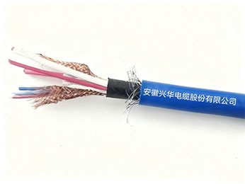
1. Product Use and Characteristics
Computer cables for coal mines are mainly used in mine safety monitoring systems, production automation control systems, and computer distributed control systems. They integrate flame retardancy, explosion protection, anti-interference, high mechanical strength, and environmental tolerance, and are an indispensable infrastructure for building modern, intelligent, and safe mines. Their design and manufacturing standards are far higher than ordinary civil or industrial cables, with all efforts focused on ensuring the safety of coal mine production.
2. Product Standards
MT/T386-2011
3. Product Classification and Designation
Type | Name | Main Application Scope |
MDJYPV | Computer cables for coal mines | Used for connecting electronic computers and automation equipment in coal mines with high anti-interference requirements, suitable for fixed installation. |
4. Product Specifications
Type | Specification mm2 |
MDJYPV | 2×2×1.5 4×2×1.5 |
5. Technical Requirements
5.1 Conductor
5.1.1 The conductor core shall comply with the requirements of Type 1 and Type 2 in GB/T3956.
5.1.2 The conductor surface shall be smooth, free of oil stains, burrs, sharp edges that may damage the insulation, as well as raised or broken single wires.
5.1.3 The DC resistance of the conductor at 20℃ shall comply with the requirements of Table 3.
Table 3 Conductor Structure and DC Resistance
Conductor | DC Resistance at 20℃ | Nominal Insulation Thickness mm | ||
Nominal Cross-sectional Area mm2 | Conductor Type | Conductor Structure | Resistance ≤ Ω/km | |
1.5 | 1 | 1/1.38 | 12.1 | 0.6 |
1.5 | 2 | 7/0.52 | 12.1 | 0.6 |
5.2 Insulation
5.2.1 Polyethylene insulation compound shall be used, and its performance shall comply with the provisions of GB/T11115.
5.2.2 The insulation shall be extruded tightly onto the conductor, easily strippable without damaging the insulation body. The surface shall be smooth, uniformly colored, free from cracks and other damage.
5.2.3 The nominal insulation thickness shall comply with the provisions of Table 3. The average thickness shall not be less than the nominal value, and the minimum thickness at any point shall not be less than 90% of the nominal value minus 0.1 mm.
5.2.4 Color identification markers shall be used for insulated cores. The colors shall comply with GB/T6995 and shall not migrate or fade.
5.3 Insulation Performance Requirements
5.3.1 The insulated core shall withstand the AC spark test as specified in GB/T 3048.9 as an intermediate inspection. The spark test voltage shall be 6 kV.
5.3.2 The mechanical properties of the cable insulation shall comply with the requirements of Table 4.

Table 4 Physical and Mechanical Properties of Insulation and Sheath
No. | Test Item |
Unit | Technical Requirements | |
Polyethylene Insulation | PVC Outer Sheath | |||
1 | Mechanical properties before aging | |||
1.1 | Tensile strength ≥ | N/mm2 | 10.0 | 12.5 |
1.2 | Elongation at break ≥ | % | 300 | 150 |
2 | Air oven aging test (GB/T2951.12) Treatment conditions — Temperature (tolerance ±3℃) |
℃ |
- |
100 |
2.1
2.2 | — Time Change rate of tensile strength after aging Change rate of elongation at break after aging |
≥ ≤ ≥ ≤ | h N/mm2 % % % | - - - - - | 168 12.5
±25 150 ±25 |
5.4Cabling Elements
5.4.1 Structure of cabling elements
Pair group — Two insulated conductors twisted together, respectively marked as a-line and b-line;
5.4.2 Insulated cores shall be twisted into groups. The maximum lay length shall not exceed 25 times the outer diameter of the twisted group.
5.4.3 Identification of cabling elements
Cabling elements may use color tapes, numbers, or color codes for identification. If color codes are used, recommended pair color codes are blue/white, red/white, green/white, red/blue, with the blue/white pair as the marker pair. Multi-pair cables may use color tapes or number identification.
5.5 Individual screen for cabling elements
The individual screen shall adopt a copper wire braided structure, with a single wire diameter not less than 0.12 mm, and a braid density not less than 80%. The braid density is calculated according to 5.7.2.
5.6 Core structure
5.6.1 Core stranding
The core shall be stranded in concentric layers, with adjacent layers in opposite directions. The outermost layer shall be right-handed. The lay length of the core shall not exceed 25 times the outer diameter of the stranded core.
5.6.2 Core wrapping
The core shall be lapped with one layer of 0.05 mm thick polyester tape. Other non-hygroscopic tape materials that do not melt at the cable's maximum rated operating temperature may also be used. The lapping overlap shall not be less than 50%; or two layers may be lapped with an overlap not less than 25%.
5.7 Overall screen
5.7.1 The overall screen of the core shall adopt copper wire braiding. The braiding diameter shall comply with Table 5, and the braid density shall not be less than 80%.
Table 5 Nominal diameter of round copper wire for braiding
Assumed diameter before braiding d/mm | Nominal diameter of round copper wire /mm | Assumed diameter before braiding d/mm | Nominal diameter of round copper wire /mm |
d≤10 | 0.15 | 20<d≤30 | 0.25 |
10<d≤20 | 0.20 | 30<d | 0.30 |
During copper wire braiding, the copper wire shall not be exposed on the braided layer. If copper wire ends are exposed, the machine should be stopped for trimming. The braided layer shall not be welded as a whole. Note:The assumed diameter calculation method is in accordance with Appendix A of GB/T9330.1 (same below).
Where: Assumed outer diameter of pair group
d = Dc × 2 + 2δ · · · · · · · · · · · · · · · · · · · · · · · · · · · · · · · · · · · · · · (1)
Where: Dc—Assumed diameter of insulated core;
δ—Nominal thickness of the individual screen layer, its value as per Appendix A.2.4 of GB/T9330.1.
Stranded core outer diameter: for pair groups: Dp=dp ×k×cf mm
cf: individual screen is 0.89, overall screen is 0.82;
K is the stranding coefficient, see Appendix A of GB/T9330.1.
5.7.2 Braid density (K), expressed as a percentage, is determined by formula (3):
Where: K——— Braid density, %;
kf ——— One-way coverage coefficient; L———— Braiding pitch, mm;
D ——— Average diameter of braid, mm; d ———— Diameter of round copper wire, mm;
m ———— Number of spindles;
n ———— Number of strands per spindle.
5.7.3 One layer of 0.05 mm thick polyester tape may be lapped outside the overall screen. Other non-hygroscopic tape materials that do not melt at the cable's maximum rated operating temperature may also be used.
5.8 Cable outer sheath
The outer sheath color shall be blue. The material shall be flame-retardant PVC compound, with performance meeting the requirements of GB/T 8815.
5.8.1 Outer sheath thickness
The nominal sheath thickness TS (in mm) shall be calculated according to formula (4):
TS = 0.035D + 1.0 · · · · · · · · · · · · · · · · · · · · · · · · · · · · · · · · · · · · · · · · · · · · · · · (4)
Where: D—Assumed diameter of the cable before sheath extrusion, mm
The value calculated by the above formula shall be rounded to 0.1 mm according to GB/T8170.
The average sheath thickness shall not be less than the nominal value. The minimum nominal sheath thickness shall not be less than 1.2 mm, and the minimum thickness at any point shall not be less than 85% of the nominal value minus 0.1 mm.
5.8.2 The physical and mechanical properties of the cable outer sheath shall comply with the requirements of Table 5.
6 Finished cable
6.1 Cable outer diameter
The cable outer diameter shall comply with the requirements of Table 6 (maximum outer diameter).
Table 6 MDJYPV type cable
Number of pairs × cores × nominal cross-section mm2 | Type 1 conductor | Type 2 conductor |
Average outer diameter ≤ mm | Average outer diameter ≤ mm | |
2×2×1.5 | 17.7 | 18.3 |
4×2×1.5 | 18.2 | 18.8 |
6.2 The cable conductor core shall have no broken wires, inter-pair continuity, or short circuits.
6.3 The physical and mechanical properties of the finished cable insulation shall comply with the requirements of 5.3.2; the physical and mechanical properties of the finished cable sheath shall comply with the requirements of 5.8.2.
6.4 For the voltage test of the finished cable, the cable cores or cores to screen shall withstand a power frequency AC voltage of 1500V for 1 min without breakdown.
6.5 Insulation resistance
6.5.1 The insulation resistance of each conductor to be measured relative to the other conductors/ screen/armor connected together shall be measured with a DC voltage of 500V. After a stable charging time of 1 min, it shall not be less than 3000 MΩ·km at 20℃.
6.5.2 For cables with individually shielded pairs, using a DC voltage of 500V, after a stable charging time of 1 min, the insulation resistance between shields shall not be less than 1 MΩ·km at 20℃.
6.6 Capacitance
The capacitance at 1 kHz of the cabling element shall not exceed 125 pF/m. 6.7 Capacitance unbalanceThe maximum capacitance unbalance of shielded cable pairs to ground shall not exceed 500 pF for a length of 250 m at a frequency of 1 kHz. For lengths other than 250 m, the measured value shall be corrected as follows: multiply the measured value by 250/L, where L is the cable length in meters. Lengths less than 100 m shall be considered as 100 m.
6.8 The cable attenuation shall not exceed 1.2 dB/km.
6.9 The far-end crosstalk attenuation between any two pairs over a length of 500 m shall not be less than 70 dB.6.10 The inductance per core over a length of 1 km shall not exceed 800 μH.
6.11 Low-temperature static bending performance
The cable shall withstand a low-temperature static bending test at -40℃. After the test, there shall be no visible cracks or openings on the cable surface.
6.12 Low-temperature impact test
The cable shall withstand a low-temperature impact test at -10℃. After the test, there shall be no damage on the cable surface, and no short or open circuits between cores.
6.13 Low-temperature tensile test
The test temperature is -10℃.
6.14 High-temperature testThe cable shall withstand a high-temperature test. After the test, there shall be no visible cracks or openings on the cable surface.
6.15 Damp heat testThe cable shall withstand a damp heat test. The high temperature is +40℃, with a cycle of 6 days. Immediately after the test, the insulation resistance shall not be less than 100 MΩ·km, and the cores shall withstand a power frequency voltage of 1.5 kV for 1 min without breakdown. The cable surface shall have no wrinkles, bubbles, or cracks.
6.16 Flame retardant performance
The cable flame retardant performance shall meet the test requirements specified in 4.2 and 4.3 of MT/T386.6.17 Delivery lengthDelivery length shall be as agreed upon by both parties. The length measurement error shall not exceed ±0.5%.
7 Test methods and inspection rules
7.1 Inspection classification
The inspection of cables is divided into type tests, sample tests, and routine tests.
7.2 Type test (T)A type test shall be performed under any of the following circumstances:
1) Type test verification for new products or old products transferred to a new factory;
2) After formal production, if there are major changes in the process, formulation, or structure that may affect product performance;
3) When renewing the product inspection certificate;
4) When there is a dispute over product quality between the supplier and the buyer that requires arbitration;
5) When the state quality and technical supervision department requests inspection.
Cables used in coal mines must undergo type tests by a nationally accredited testing center in accordance with this standard, and obtain a "Product Test Report".
7.3 Sample test (S)
At least one sample shall be taken from each delivery batch for sample testing. The sample test items may also be specified by agreement between the supplier and the buyer.
If a sample test item fails, double the number of samples shall be taken for a second test of the failed item. If it still fails, each product in the batch shall be tested individually.
7.4 Routine test (R)
Products may leave the factory only after inspection by the manufacturer's quality inspection department and issuance of a quality inspection certificate. The quality inspection certificate shall at least include the following:
a)Manufacturer's name;
b) Product type and specification;
c)Length (m);
d) Date of manufacture or production batch number;
e)Standard number;
f)Safety mark and certificate number;
g) Quality inspection seal.
7.5 Finished cables shall be tested in accordance with Table 7 to verify compliance with the corresponding requirements.
Table 7 Test methods
No. | Test item | Clause No. | Test category | Test method |
1 | Electrical performance | |||
1.1 | Conductor resistance (20℃) | 5.1.3 | T, S | GB/T 3048.4 |
1.2 | Conductor continuity test | 6.2 | T, R | MT/T 818.14 |
1.3 | Finished cable voltage test | 6.4 | T, R | GB/T 3048.6 |
1.4 | Insulation resistance (20℃) | 6.5 | T | GB/T 3048.8 |
1.5 | Capacitance | 6.6 | T | MT/T 818.14 |
1.6 | Capacitance unbalance | 6.7 | T | GB/T 5441 |
1.7 | Attenuation | 6.8 | T | MT/T 818.14 |
1.8 | Crosstalk attenuation | 6.9 | T | MT/T 818.14 |
1.9 | Inductance | 6.10 | T | MT/T 818.14 |
2 | Structural dimensions | |||
2.1 | Surface marking | 7.6 | T, S | MT/T 818.14 |
2.2 | Insulation thickness | 5.2.3 | T, S | GB/T 2951.11 |
2.3 | Sheath thickness | 5.8.1 | T, S | GB/T 2952.11 |
2.4 | Cable outer diameter | 6.1 | T, S | GB/T 2951.11 |
3 | Insulation physical and mechanical properties | 6.3 | T | GB/T2951.11, GB/T 2951.12, GB/T 2951.14, GB/T 2951.31 and GB/T 2951.32 |
4 | Sheath physical and mechanical properties | 6.3 | T | |
5 | Low temperature performance test | |||
5.1 | Low temperature bending test | 6.11 | T | MT/T 818.14 |
5.2 | Low temperature impact test | 6.12 | T | GB/T2951.14 |
5.3 | Low temperature tensile test | 6.13 | T | GB/T2951.14 |
6 | High temperature test | 6.14 | T | MT/T 818.14 |
7 | Damp heat test | 6.15 | T | MT/T 818.14 |
8 | Flame retardant test | |||
8.1 | Single vertical combustion test | 6.16 | T, S | MT/T 386 |
8.2 | Bunched combustion test | 6.16 | T | MT/T 386 |
9 | Delivery length | 6.17 | R | Length measuring device |
7.6 Marking
7.6.1 Product marking shall be applied on the cable sheath surface by embossing or using ink that contrasts in color with the sheath. The product marking shall include the following:
a)Manufacturer's name;
b)Cable type, specification, and rated voltage;
c) Safety mark and certificate number.
7.6.2 The marking must be clear and abrasion-resistant, with spacing not exceeding 1 m.
7.6.3 Other markings may be set inside or outside the cable, but their use shall not compromise the conspicuousness and clarity of the required marking. Finished cable marking shall comply with GB/T6995.
8 Packaging, Transport, and Storage
8.1 Packaging
Each coil or reel shall be provided with a label indicating the following:
a)Manufacturer's name;
b) Product type, specification, and rated voltage;
c)Length (m);
d) Date of manufacture or production batch number;
e)This standard number;
f) Safety mark and certificate number;
8.2 The cable shall be delivered in coils or on reels. The bending radius shall comply with the following: The drum diameter of the cable reel shall be at least 8 times the cable outer diameter.
8.3 Both ends of the cable must be sealed. The weight of a coil-packaged cable shall not exceed 80 kg.
8.4 Cables delivered on reels shall be neatly wound on cable reels that comply with JB/T8137. The reel shall indicate the correct direction of rotation. The reel shall be protected with bamboo slats or other suitable materials.
8.5 Transport and Storage
The cable shall be suitable for all modes of transport including water, land, and air. Warning:
a)Prevent moisture ingress into the cable;
b) Prevent severe bending and other mechanical damage;
c)Prevent exposure to high temperatures and direct sunlight.
If you are interested in our products, or want to ask related questions, please leave a message to us.
We will reply and serve you as soon as possible. Thank you for visiting our official website.