
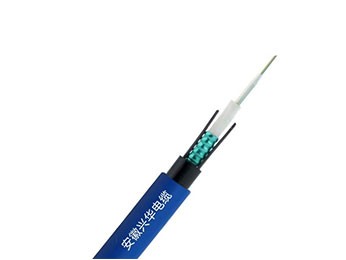
I. Product Application and Features
Mining CommunicationOpticalCable is the core transmission medium primarily used to ensure safe coal mine production and promote intelligent mining. It integrates safety features such as flame retardancy, explosion protection, rugged durability, moisture resistance, and corrosion resistance, while leveraging the technical advantages of optical fiber including high capacity, anti-interference, and long-distance transmission, providing an ideal solution for building reliable and efficient mine communication networks.
II. Product Standards
GB/T 2951.11-2008
III. Product Modeland Name
Model | Name | Applicable Occasion |
MGTS | Mining Communication Optical Cable | For use in horizontal roadways and inclined shafts with high interference |
MGXTW | Mining Communication Optical Cable | For use in horizontal roadways and inclined shafts with high interference |
MGXTSV | Mining Communication Optical Cable | For use in horizontal roadways and inclined shafts with high interference |
Table1
IV.Product Specifications
4 Specifications
The single-mode optical fibers in the cable shall comply with GB/T 9771 regarding Class B1.1, B1.3, B4, B5, B6, or
Class B1.2e single-mode optical fibers. Multimode optical fibers shall comply with the provisions for Class A1a and A1b multimode optical fibers specified in GB/T12357.
3.3.2 The optical fibers in stranded loose tube cables should be 2, 4, 6, 8, 10, 12, 14, 16, 18, 20, 24, 30, 36, 48, 60, 72, 84, 96, 108, 120, 132, or 144 fibers; the optical fibers in central tube cables should be 2, 4, 6, 8, 10, 12.
5 Product Model and Marking
5.1 Model
The optical cable model consists of the cable type and specification, separated by a space.
5.2 Marking
When placing an order, the optical cable product marking shall be indicated, which consists of the cable model and the number of this standard.
V. Technical Requirements
5.1 Structure
5.1.1 General
5.1.1.1 The structure of stranded loose tube optical cable consists of two main parts: the stranded cable core and the protective layer. The protective layer includes the sheath and possible outer protective layer. The structure of central tube optical cable consists of optical fibers, central tube, strength member, water-blocking material, and protective layer. The protective layer includes the sheath and possible outer protective layer. See the structural diagram for details.
5.1.1.2 The optical cable structure shall be fully water-blocked, i.e., water cannot flow longitudinally in the cable core or protective layer. However, the steel wire armoring part,and the non-metallic rod, tape, or wire armoring part may be excluded. The water-blocking structure may adopt two methods:
Filled type: All gaps within the optical cable sheath or possible inner liner are continuously filled with a paste compound.
Semi-dry type: The gaps within the optical fiber loose tubes are continuously filled with a paste compound, and solid water-blocking materials are placed in other gaps within the cable.
5.1.1.3 Other similar structural types are permitted, but the sheath thickness and cable performance requirements of such cables shall still not be lower than the relevant provisions of this standard. If other similar types are adopted, they shall be specified in other enterprise standards or in the revision of this standard.
5.1.1.4 Optical cable products of the same batch and same type/specification shall have the same structural arrangement and the same identification color code.
5.1.2 Cable Core
5.1.2.1 General Description
The stranded loose tube cable core typically includes a central strength member (including possible padding layer), stranded loose tube fiber layer (including possible filler rope), possible wrapping tape and binding yarn, non-metallic auxiliary strength member, polyethylene inner liner, and armoring steel wire, etc.
5.1.2.2 Optical Fiber
5.1.2.2.1 The optical cable shall be composed of coated single-mode optical fibers of the same type or multimode optical fibers composed of glass core and glass cladding. The fiber count shall comply with the cable specification requirements. Optical fibers used in the same batch of cable products shall be manufactured with the same design, same materials, and same process.
5.1.2.2.2 The surface of the optical fiber coating shall have full-color color codes. The colors shall comply with GB/T6995.2-2008 and shall not fade or migrate.Migration is not permitted. The natural color of the optical fiber may be used as a substitute for white.
5.1.2.2.3 The performance of single-mode optical fibers used for cabling shall comply with the relevant provisions of GB/T 9771, and multimode optical fibers shall comply with the relevant provisions of GB/T12357.
5.1.2.3 Loose Tube and Filling Compound
5.1.2.3.1 The loose tube shall be made of thermoplastic material, which provides mechanical buffering and protection for the coated optical fibers. Loose tube materials may include polybutylene terephthalate (PBT), modified polypropylene plastic (PP), or other suitable plastics. PBT shall comply with YD/T1118.1, PP performance shall comply with YD/T1118.2, and detailed technical specifications for other materials shall be specified separately.
5.1.2.3.2 When the number of optical fibers in each loose tube does not exceed 12, the fibers in the tube shall be identified using the full color code. The colors shall be selected according to Table2, and the natural color may be used when it does not affect identification.
Table 2 Full Color Code for Identification
No. : | 1 | 2 | 3 | 4 | 5 | 6 | 7 | 8 | 9 | 10 | 11 | 12 |
Col or | Blue | Orange | Green | Brown | Gray | White | Red | Black | Yellow | Violet | Pink Red | Cyan Green |
5.1.2.3.3 The dimensions of the loose tube shall specify the outer diameter and wall thickness.
The nominal outer diameter of optical fiber loose tubes shall be 1.8~3.0 mm, with tolerance not worse than ±0.1 mm; the thickness shall increase with the outer diameter, with a nominal value of 0.30~0.50 mm and tolerance not worse than ±0.05 mm;
The nominal outer diameter of central tube optical fiber loose tubes shall be 1.8~8.0 mm, with thickness increasing with outer diameter, and a nominal value of 0.8~1.2 mm. When the nominal outer diameter is 1.8~4.0 mm (including 4.0 mm), the nominal outer diameter tolerance shall be ±0.10 mm, and the thickness tolerance shall be ±0.05 mm; when the nominal outer diameter is 4.0~8.0 mm, the nominal outer diameter tolerance shall be ±0.20 mm, and the thickness tolerance shall be ±0.10 mm;
The nominal dimensions of the loose tube may vary with the number of optical fibers in the tube, but shall be the same within the same optical cable.
5.1.2.2.4 The loose tube shall have identification color codes. The colors shall comply with GB/T 6995.2 and shall not fade or migrate. These color codes should be full-color, or may be ring-shaped or strip-shaped color codes
5.1.2.2.5 The excess fiber length in the loose tube shall be uniform and stable,so that the tensileperformance and attenuation temperature characteristics of the cable comply with this standardrequirements.
5.1.2.2.6 The gaps within the loose tube shall be continuously filled with a thixotropic paste compound, i.e., fiber gel.
5.1.2.2.7 The fiber gel shall be compatible with the adjacent fiber coating and loose tube material, and shall not impair the transmission characteristics and service life of the optical fibers,The fiber gel shall comply withYD/T839.2-2014 requirements.
5.1.2.4 Filler Rope
The filler rope is used to fill vacant positions in the stranded loose tube fiber layer, and its outer diameter shall make the cable core round. The filler rope shall be a circular solid plastic rope with a smooth and round surface, compatible with adjacent cable components.
5.1.2.5 Strength Member
5.1.2.5.1 General
The strength member of stranded loose tube optical cable shall be at the center of the cable. It may be metallic or non-metallic, depending on the cable type. When necessary, non-metallic auxiliary strength members may be placed at appropriate positions around the cable core. These strength members shall have sufficient cross-section, Young's modulus, and elastic strain range to enhance the tensile performance of the cable.
The strength member of central tube optical cable shall be in the sheath or outside the central tube within the sheath. It may be metallic or non-metallic. These strength members shall have sufficient cross-section, Young's modulus, and elastic strain range to ensure that the tensile performance and attenuation temperature characteristics of the cable comply with the provisions of this standard.
5.1.2.5.2 Metallic strength members should preferably be high-strength single round steel wires, or steel strands composed of high-strength steel wires. High-strength steel wires should preferably be phosphated steel wires or stainless steel wires with smooth and round surfaces. The Young's modulus of single steel wire shall be not less than 190 GPa, and its performance shall comply with GB/T24202. Steel strands shall be phosphated steel strands with an effective Young's modulus not less than 170 GPa. Other properties shall comply with YB/T098. Within the manufacturing length of the optical cable, single round steel wires shall have no joints, and in steel strands, only one joint is allowed for one single steel wire within any 200 m cable length.
5.1.2.5.3 Non-metallic strength members should preferably be glass fiber reinforced plastic (GFRP) round rods or aramid fiber reinforced plastic (KFRP) round rods. GFRP shall comply with YD/T1181.1, and KFRP shall comply with YD/T 1181.3. Non-metallic auxiliary strength members should preferably be aramid yarn or glass fiber yarn. Aramid yarn shall comply with YD/T1181.2, and glass fiber yarn shall comply with YD/T1181.4. Other high-strength fiber bundles harmless to the human body may also be used. Within the manufacturing length of the optical cable, GFRP and KFRP shall not have joints. Each bundle of aramid yarn is allowed one joint, but only one joint is allowed within any 200 m length.
5.1.2.5.4 When steel wire rope is used, an extruded plastic cushion layer of appropriate thickness shall be applied on its surface, and appropriate water-blocking measures shall be adopted under the cushion layer to prevent longitudinal water seepage through the gaps of the steel wire rope. When single steel wire is used, an extruded plastic cushion layer of appropriate thickness may also be applied on its surface. The cushion layer surface shall be smooth and round, with an appropriate outer diameter, and its material shall be compatible with the filling compound.
5.1.2.6 Stranding Layer
5.1.2.6.1 The same stranding layer shall be formed by stranding loose tubes (including possible filler ropes) of the same outer diameter around the central strength member with an appropriate pitch. The number of loose tubes (including possible filler ropes) should preferably be 5~12 units. The stranding may be helical stranding or SZ stranding.
5.1.2.6.2 The identification of loose tubes in the stranding layer may adopt the full color code method or the pilot color code method.
——When the full color code is adopted, viewing from end A of the optical cable, the loose tube serial number increases in the clockwise direction. The loose tube serial numbers and their correspondingcolors shall comply with the provisions of Table 2.
——When the pilot color code is adopted, the pilot colors shall be red and green, and the remaining elements shall be other identical colors, preferably the natural color. Viewing from end A of the optical cable, red and green are arranged in sequence in the clockwise direction and the loose tube serial number increases (filler ropes are not counted in the serial number). When a loose tube is red, serial number 1 is red; when there is no red loose tube, serial number 1 is the first loose tube after the pilot red.
5.1.2.7 Binding Yarn
5.1.2.7.1 When helical stranding is adopted, the stranding layer may or may not have short-pitch binding yarn with a lay direction opposite to that of the stranding layer.
5.1.2.7.2 When SZ stranding is adopted, the stranding layer shall have short-pitch binding yarn or other methods to fix the stranding layer, to ensure structural stability of the stranding layer.
5.1.2.7.3 The binding yarn shall be a non-hygroscopic and non-oil-absorbing plastic yarn bundle with sufficient strength, or water-blocking yarn.
5.1.2.8 Wrapping Tape Layer
5.1.2.8.1 The outside of the cable core stranding layer may have a wrapping tape layer applied by helical wrapping or (and) longitudinal wrapping. Binding yarn is allowed outside the longitudinal wrapping layer. The wrapping tape layer shall have sufficient heat insulation and voltage withstand performance.
5.1.2.8.2 The wrapping tape material shall be polyester tape, polyester non-woven tape, water-swellable tape, or other suitable tape material with sufficient strength.
5.1.2.9 Water-Blocking Structure
5.1.2.9.1 All gaps within the optical cable sheath shall have effective water-blocking measures. For the cable core gaps within the wrapping tape (or inner liner), fully filled cables shall be continuously filled with paste compound (cable gel). For the gaps between the wrapping tape (or inner liner) and the sheath, coatedcompound continuous filling or continuous placement of water-blocking tape, water-blocking powder, or water-blocking yarn may be used, or water-blocking rings may be installed at intervals.
5.1.2.9.2 The cable gel shall comply with YD/T839.3-2014, and water-blocking tape and water-blocking yarn shall comply with YD/T1115.
5.1.3 Sheath
5.1.3.1 General
5.1.3.1.1 Common sheaths for optical cables include steel-plastic bonded sheath (S sheath), polyethylene sheath (Y sheath), and steel-plastic bonded sheath with parallel strength members (W sheath).
5.1.3.2 Steel-Plastic Bonded Sheath (hereinafter referred to as S-sheath)
5.1.3.2.1 S-sheathed optical cables shall have a longitudinally wrapped overlapped corrugated steel-plastic composite tape moisture barrier layer applied over the cable core, and simultaneously be extruded with a black polyolefin sheath, so that the polyethylene sheath and the composite tape, as well as the composite tape at the overlapped edges, shall be mutually bonded into one body. If necessary, adhesive may be applied at the overlap to enhance bonding strength. The corrugations of the composite tape after longitudinal wrapping shall be annular. The overlap width shall be not less than 5mm, or not less than 20% of the cable core circumference when the diameter before longitudinal wrapping is less than 8.0mm. The nominal thickness of the polyethylene sheath shall be 1.8mm, with a minimum value of not less than 1.5mm, and the average value on any cross-section shall be not less than 1.6mm. For MGXTSV products, the nominal thickness of the polyolefin sheath shall be 1.0mm, with a minimum value not less than 80% of the nominal value, and the average value not less than 90% of the nominal value.
5.1.3.2.2 The steel-plastic composite tape shall be a double-sided steel-plastic composite tape conforming to YD/T 723.3-2007. The minimum thickness of the steel strip shall be not less than 0.13 mm, and the nominal thickness of the plastic composite layer shall be 0.05 mm. A small number of composite tape joints are permitted along the manufacturing length of the optical cable; the steel strips at the joints should be butt-jointed, and the distance between joints shall be not less than 350m. The joints shall be electrically conductive and the plastic composite layer shall be restored. The strength of the composite tape containing joints shall be not less than 80% of the strength of the adjacent joint-free section.
5.1.3.3 Steel-Plastic Bonded Sheath with Parallel Strength Members (hereinafter referred to as W-sheath).
WThe sheath shall have a longitudinally wrapped overlapped steel-plastic composite tape moisture barrier layer applied over the central tube, and simultaneously be extruded with a layer containing parallel steel wire or non-metallic fiber-reinforced plastic rods in a black plastic sheath; the plas--tic sheath and the composite tape, as well as at the overlapped edges of the composite tape, shall be mu- tually bonded into one body. The composite tape may be either non-corrugated or corrugated, and its overlap width shall be not less than5mm, or when the cable core diameteris less than8.0mm, the overlap width shall be not less than the cable core circumference20%. The requirements for the steel-plastic composite tape are the same as in4.1.3.3.2. From the outer edge of the strength member to the plas--tic outer edge of the sheath, the nominal plastic thickness shall be1.0mm, and the minimum value shall be not less than0.8mm, and the average value shall not beis less than0.9mm。
5.1.4 Outer Sheath
The MGXTSV outer sheath is based on various types of sheaths or armors, with an additional outer layer of flame-retardant grade PVC sheath or flame-retardant polyolefin sheath to provide fire prevention and flame retardancy. Its surface shall be complete and smooth. The nominal thickness of the sheath shall be 1.8mm, and the minimum valueshall be not less than1.5mm, and the average value on any cross-section shall be not less than1.6mm。
5.1.5 Delivery Length
The standard manufacturing length of optical cables shall be nominally 2000 m, 3000 m, or 4000 m, with a tolerance of 0~+100 m. The delivery length of optical cables shall be the standard manufacturing length. With the buyer's consent, delivery may be made in any length.
5.2 Performance Requirements
5.2.1 Fiber Characteristics
5.2.1.1 Characteristics of Single-Mode Fibers in Optical Cables
Single-mode fibers in optical cables shall comply with the provisions for Class B1.1, Class B1.3, Class B4, Class B5, Class B6, or Class B1.2esingle-mode fibers specified in GB/T 9771.
5.2.1.1.1 The dimensional parameters of single-mode fibers shall comply with the provisions in Table 3.

Table 3 Single-Mode Fiber Dimensional Parameters
Fiber Type | B1.1 | B1.3 | B4 | B5 | B6 | B1.2e | |
Cladding Diameter | Nominal Value (µm) | 125.0 | |||||
Tolerance (µm) | ± 1.0 | ±0.7 | ± 1.0 | ||||
Cladding Non-Circularity(%) | ≤ 1.0 | ≤ 2.0 | ≤ 1.0 | ≤ 1.0 | |||
Core Concentricity Error (µm) | ≤ 0.6 | ≤ 0.8 | ≤ 0.5 | ≤ 0.6 | |||
Coating Diameter | Nominal Value (µm) | 245 | |||||
Tolerance (µm) | ± 10 | ||||||
Cladding/Coating Concentricity Error (µm) | ≤ 12.5 | ||||||
5.2.1.1.2 The mode field parameters of single-mode fibers shall comply with the provisions in Table 4.
Table 4 Single-Mode Fiber Mode Field Diameter Parameters
Fiber Type | B1.1 | B1.3 | B4 | B5 | B6 | B1.2e | |
Mode Field Diameter | Wavelength (nm) | 1310 | 1550 | 1310 | 1550 | ||
Nominal Value(µm) | 8.6~9.5 | 8.0~11.0 | 7.0~11.0 | 8.6~ 9.5 | 11.5~12.5 | ||
Tolerance(µm) | ±0.6 | ±0.6 | ±0.7 | ± 0.4 | ± 0.5 | ||
5.2.1.1.3 The cable cut-off wavelength λCC shall comply with the provisions in Table 5.
Table 5 Cable Cut-Off Wavelength Unit:nm
Fiber Type | B1.1 | B1.3 | B4 | B5 | B6 | B1.2e |
λCC | ≤1260 | ≤1450 | ≤1260 | ≤1530 | ||
5.2.1.1.4 The attenuation characteristics of single-mode fibers shall comply with the provisions in Table 6.
Table 6 Attenuation Characteristics
Fiber Type | B1.1、B1.3、B6 | B4 and B5 | B1.2e | ||||
Operating Wavelength (nm) | 1310 | 1550 | 1460 | 1550 | 1625 | 1550 | 1625 |
Attenuation Coefficient(Maximum Value) (dB/km) | 0.40 | 0.25 | 0.40 | 0.25 | 0.30 | 0.23 | 0.40 |
5.2.1.1.5 The dispersion characteristics of single-mode fibers shall comply with the provisions in GB/T 9771.
5.2.1.2 Characteristics of Multimode Fibers in Optical Cables
Multimode fibers in optical cables shall comply with the provisions for Class A1a and Class A1b multimode fibers specified in GB/T 12357.
5.2.1.2.1 The dimensional parameters of multimode fibers shall comply with the provisions in Table 7.
Table 7 Multimode Fiber Dimensional Parameters
Fiber Type | A1a | A1b | |||
Core Diameter | Nominal Value(µm) | 50.0 | 62.5 | ||
Tolerance(µm) | ±2.5 | ±2.5 | |||
Cladding Diameter | Nominal Value(µm) | 125 | 125 | ||
Tolerance(µm) | ±2 | ±2 | |||
Cladding Non-Circularity(%) | ≤2 | ≤2 | |||
Core/Cladding Concentricity Error (µm) | ≤1.5 | ≤1.5 | |||
Coating Diameter | Nominal Value(µm) | 245 | 245 | ||
Tolerance(µm) | ±10 | ±10 | |||
Colored Layer Diameter | Nominal Value(µm) | 250 | 250 | ||
Tolerance(µm) | ±15 | ±15 | |||
Cladding/Coating Concentricity Error (µm) | ≤12.5 | ≤12.5 | |||
5.2.1.2.2 The numerical aperture of multimode fibers shall comply with the provisions in Table 8.
Table8 Numerical Aperture
Fiber Type | A1a | A1b |
Numerical Aperture | 0.200±0.015 | 0.275±0.015 |
5.2.1.2.3 The transmission characteristics of multimode fibers shall comply with the provisions in Table 9.
Table9 Multimode Fiber Transmission Characteristics
Item | Unit | A1a.1 | A1a.2 | A1a.3 | A1b | |
Maximum Attenuation Coefficient | 850nm | dB/km | 3.5 | 3.5 | ||
1300nm | 1.5 | 1.5 | ||||
Minimum Modal Bandwidth | 850nm | MHz·km | 200~800 | 1500 | 3500 | 160~800 |
1300nm | 200~1200 | 500 | 200~1000 | |||
5.2.2 Sheath Performance
5.2.2.1The moisture barrier steel tape and the metallic armor layer shall be electrically conductive along the longitudinal direction of the optical cable respectively.
5.2.2.2The peel strength between the steel tape and the polyethylene sheath of the bonded sheath (including Type 53 outer sheath) shall be not less than 1.4 N/mm.
5.2.2.3The mechanical and physical characteristics of the sheath and outer sheath shall comply with the provisions in Table 10; other properties shall comply with the relevant provisions in GB/T 2952.
5.2.3 Mechanical Properties of Optical Cables
5.2.3.1The mechanical properties of optical cables shall include tensile, crush, impact, repeated bending, torsion, and winding tests, and shall be verified by the test methods and test conditions specified in 5.5.
5.2.3.2The permissible tensile force and crush force that optical cables can withstand shall comply with the provisions in Table 11.
Table10 Mechanical and Physical Properties of Inner and Outer Sheaths
No. | Item | Unit | Property | |
PVC | ZRPE | |||
1 | Tensile Strength Before Thermal Aging (Minimum Value) Change Rate Before and After Thermal Aging|TS|(Maximum Value) Thermal Aging Treatment Temperature Thermal Aging Treatment Time | MPa% | 12.520 | 10.020 |
℃h | 100±2 | |||
240 | 240 | |||
2 | Elongation at Break Before Thermal Aging (Minimum Value) After Thermal Aging (Minimum Value) Change Rate Before and After Thermal Aging|EB|(Maximum Value) Thermal Aging Treatment Temperature Thermal Aging Treatment Time | %%% | 150 125 20 | 220 180 20 |
℃h | 100±2240 | 100±2240 | ||
3 | Heat Shrinkage (Maximum Value) Heat Treatment Temperature Heat Treatment Time | % | 5 | |
℃h | 110±22 | 100±24 | ||
4 | Environmental Stress Crack Resistance (50°C, 96 h) (Number of Failures/Number of Specimens) | pcs | 0/10 | |
Table11 Permissible Tensile Force and Crush Force of Optical Cables
Model | Permissible Tensile Force (Minimum Value) | Permissible Crush Force (Minimum Value) | ||
FST(N) | FLT(N) | FSC(N/100mm) | FLC(N/100mm) | |
MGTS | 1500 | 600 | 1000 | 300 |
MGXTW | 1500 | 600 | 1000 | 300 |
MGXTSV | 3000 | 1000 | 3000 | 1000 |
Note:FST-Short-term tensile force;FLT-Long-term tensile force;FSCShort-term crush force;FLC-Long-term crush force. | ||||
5.2.3.3 The minimum permissible bending of optical cables shall be expressed as a multiple of the cable outer diameter D, and shall comply with the provisions in Table 12. Table 12 Minimum Permissible Bending Radius of Optical Cables
MGTSV、MGXTW | MGXTSV | |
Static bending(during long-term operation) | 10D | 12.5D |
Dynamic bending(during installation) | 20D | 25D |
5.2.4 Environmental performance of optical cable
The environmental performance of the optical cable shall include attenuation temperature characteristics、drip flow performance、sheath integrity、water permeability、flame retardancy、bending performance at low temperature、impact performance at low temperature and sheath integrity and other items,and shall be verified by the test methods and test conditions specified in 5.6。
5.2.4.1Applicable temperature range and its attenuation temperature characteristics
The applicable temperature range of the optical cable and the allowable temperature-induced additional attenuation of its optical fibers relative to 20℃ shall comply with the requirements specified in Table 13。Table 13 Attenuation temperature characteristics of optical cable
Fiber Type | Maximum additional attenuation during testdB/km | Maximum residual additional attenuation after testdB/km | |
Single-mode fiber | At1310nmand1550nmwavelength | 0.10 | 0.05 |
Multimode fiber | At850nmwavelength | 0.5 | 0.20 |
At1300nmwavelength | 0.3 | 0.10 | |
5.2.4.2 Drip flow performance
At a temperature of 70℃,after 24h,the optical cable shall exhibit no dripping of filling compound and coating compound and similar materials。
5.2.4.3 Sheath integrity
The sheath shall be continuous and intact,when a metallic layer is present beneath it,electrical methods shall be used to conduct the sheath integrity test。The sheath shall be free of visually detectable defects and shall be continuous and intact。
5.2.4.3.1 When testing its integrity by the spark test,the polyolefin sheath shall not break down at the test voltage specified in Table 14。Table 14 Spark test voltage for polyolefin sheath
Voltage type | DC | AC |
Test voltage(minimum value) | 9t,maximum 25 | 6t,maximum 15 |
Note1:t is the nominal thickness of the sheath,mm。 Note2:The AC test voltage is the RMS value。 | ||
5.2.4.3.2 When testing its integrity by the water immersion test,the electrical performance of the polyolefin outer sheath of the optical cable after 24 hours of immersion shall comply with the following:
1)The insulation resistance to water under a DC voltage of 500V shall be not less than 2000MΩ·km。
2)The withstand voltage level shall be not less than that required to prevent breakdown for 2min under a DC voltage of 15KV。
5.2.4.4 Water penetration test
When a water head of 1 meter in height is applied to the entire cross-section of the optical cable,the cable shall be capable of preventing longitudinal water penetration。Steel wire armor,non-metallic wire armor,non-metallic tape armor,and non-metallic rod armor may be exempted from this test。
5.2.4.5 Flame retardant performance
Flame-retardant optical cables shall possess adequate flame-retardant properties,the flame retardancy of a single cable in vertical burning shall comply with the test specified in Clause 4.2 of MT/T386—2011, and the flame retardancy of bunched cables in vertical burning shall comply with the test specified in Clause 4.3 of MT/T386—2011。
5.2.4.6 Bending performance at low temperature
The optical cable shall be capable of withstanding a U-shaped bend at a bending radius of 15 times the cable diameter at a low temperature of -20ºC。5.2.4.7 Impact performance at low temperature
The optical cable shall possess impact resistance at a low temperature of -20ºC。
5.2.4.8 Overall stability performance of optical cable
During long-term use,no displacement shall occur between the sheath and the cable core。
6 Test methods
6.1 General provisions
The various properties of the optical cable shall be tested and measured by the test methods specified in Table 15 below。
Table 15 Test items、test methods、inspection categories and sampling methods
No. | Item | Clause number of this standard | Test method | Test type |
1 | Optical cable structural integrity and appearance | 5.1 | This standard6.2 | R、T |
2 | Identification color code | |||
2.1 | Optical fiber identification color code | Table2 | Visual inspection | R、T |
2.2 | Loose tube identification color code | 5.1.2.2.4 | Visual inspection | R、T |
3 | Optical cable structural dimensions | |||
3.1 | Loose tube outer diameter and wall thickness | 5.1.2.3.3 | GB/T2951.11 | S、T |
3.2 | Sheath and outer sheath thickness | 5.1.3、4.1.5 | GB/T2951.11 | S、T |
3.3 | Other structural dimensions | 5.1 | Refer toYD/T837.5—1996 | S、T |
4 | Optical cable length | 5.1.6 | This standard6.4 | R、T |
No. | Item | Clause number of this standard | Test method | Test type |
5 | Optical fiber characteristics | |||
5.1 | Dimensional parameters | 5.2.1.1.1, | GB/T15972.20,GB/T15972.21 | T |
5.2 | Mode Field Diameter | 5.2.1.2.1 | GB/T15972.45,YD/T2964-2015 | T |
5.3 | Cut-off wavelength | 5.2.1.1.2 | GB/T15972.47,YD/T2964-2015 | T |
5.4 | Attenuation Coefficient | 5.2.1.1.3 | GB/T15972.40,YD/T2964-2015 | S、T |
5.5 | Wavelength additional attenuation | 5.2.1.1.4 | GB/T15972.40,YD/T2964-2015 | T |
5.6 | Chromatic dispersion | 5.2.1.2.3 5.2.4.1 | GB/T15972.42 | T |
5.2.1.1.5 | ||||
6 | Sheath performance | |||
6.1 | Electrical continuity of metallic moisture barrier and armor layercontinuity | 5.2.2.1 | Refer toYD/T837.2--1996 Clause 5.9 | R、T |
6.2 | Tensile strength before and after thermal aging andelongation at break | Table10 Item 1、2 | YD/T837.3--1996 Clause 5.10 and 5.11 | T |
6.3 | Heat shrinkage rate | Table10 Item 3 | YD/T837.3--1996 Clause 5.12 | T |
6.4 | Environmental stress cracking of polyolefin sheath | Table10 Item 4 | YD/T837.4--1996 Clause 5.1a | T |
7 | Mechanical properties of optical cable | |||
7.1 | Tensile performance test of optical cable | 5.2.3 | This standard5.5.2 | T |
7.2 | Crush performance test of optical cable | 5.2.3 | This standard5.5.3 | T |
7.3 | Impact performance test of optical cable | 5.2.3 | This standard5.5.4 | T |
7.4 | Repeated bending test of optical cable | 5.2.3 | This standard5.5.5 | T |
7.5 | Torsion performance test of optical cable | 5.2.3 | This standard5.5.6 | T |
8 | Environmental performance of optical cable | |||
8.1 | Attenuation temperature characteristics | 5.2.4.1 | This standard5.6.1 | T |
8.2 | Drip flow performance | 5.2.4.2 | GB/T7424.2—F6(Pretreatment 1h) | T |
8.3 | Polyolefin sheath integrity(Spark test)(Water immersion) | 5.2.4.3.14.2.4.3.2 | Refer toTD/T837.4—1996 Clause 4.6This standard5.6.2 | TT |
8.4 | Water penetration performance | 5.2.4.4 | GB/T7424.2—F5B | T,S |
8.5 | Flame retardant performance (Single cable burning) (Bunched cable burning) | 5.2.4.5 5.2.4.4 | GB/T18380.12GB/T18380.35 | T,ST |
8.6 | Bending performance at low temperature | 5.2.4.6 | This standard5.6.5 | T |
8.7 | Impact performance at low temperature | 5.2.4.7 | This standard5.6.6 | T |
9 | Optical cable marking | |||
9.1 | Integrity and identifiability of marking | 5.3 | Visual inspection | R、T |
9.2 | Durability of marking | 5.3.1 | This standard5.3.1 | T |
9.3 | Meter marking error | 5.3.2 | This standard5.3.2 | T |
10 | Packaging | 7.1 | Visual inspection | R、T |
Note:Sampling types include:T stands for type test;S stands for sampling test;R stands for routine test | ||||
If you are interested in our products, or want to ask related questions, please leave a message to us.
We will reply and serve you as soon as possible. Thank you for visiting our official website.