
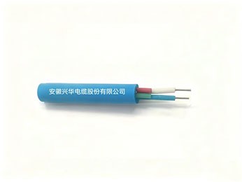
I. Product Use and Characteristics
Coal mine flame-retardant communication cables are mainly used as safety-type cables for transmitting various control, monitoring and communication signals, which possesses ultimate safety characteristics, stable transmission performance, durable mechanical and environmental performance, and is a special cable that deeply integrates communication functions with life safety. Its value lies not only in “connectivity”, but also in “safety”
II. Product Standards
MT818.14-1999
QB/DSXH001-2010
III. Product Models and Names
Model | Name |
MHYV | Coal mine polyethylene insulated polyvinyl chloride sheathed communication cable |
MHJYV | Coal mine reinforced core polyethylene insulated polyvinyl chloride sheathed communication cable |
MHYBV | Coal mine polyethylene insulated galvanized steel wire braided armored polyvinyl chloride sheathed communication cable |
MHYAV | Coal mine polyethylene insulated aluminum-polyethylene bonded shield polyvinyl chloride sheathed |
MHYA32 | Coal mine polyethylene insulated aluminum-polyethylene bonded shield steel wire armored polyvinyl chloride sheathed communication cable |
Table 1
IV. Product Specifications
Specification | MHYV | MHJYV | MHYBV | MHYAV | 4FYA32 |
Number of pairs × Number of cores | 1×2 | 1×2 | 5×2 | 20×2 | 30×2 |
2×2 | 2×2 | 10×2 | 30×2 | 50×2 | |
1×4 | — | 20×2 | 50×2 | 80×2 | |
5×2 |
Table 2
V. Technical Requirements
5.1 Conductor
5.1.1 HYV type cables use tinned soft round copper wire stranded conductors; MHJYV type cables use tinned soft round copper wire and galvanized steel wire hybrid stranded conductors; other model cables use soft round copper wire. Soft round copper wire shall comply with the provisions of GB 3953; tinned soft round copper wire shall comply with the provisions of GB4910; the galvanized steel wire conductor of hybrid stranded conductors shall comply with the provisions of Appendix B.
5.1.2 The structure of the conductor shall comply with the provisions of Tables 3~7.
Table 3 mm
Model | Specification | Conductor structure Number of strands/nominal diameter of single wire | Nominal insulation thickness | Nominal outer sheath thickness | Cable outer diameter |
M1YV | 1×2 | 7/0.28 | 0.45 | 1.6 | ≤7.1 |
2×2 | 7/0.28 | 0.45 | 1.6 | ≤8.6 | |
1×4 | 7/0.28 | 0.45 | 1.6 | ≤8.0 | |
5×2 | 7/0.28 | 0.45 | 1.6 | ≤11.5 |
Table 4
Model | Spec ification | Conductor structure Number of strands/nominal diameter of single wire | Nominal insulation thickness | Nominal outer sheath thickness | Cable outer diameter |
MHJYV | 1×2 | 4/0.28 copper wire+3/0.28 steel wire | 0.45 | 1.6 | ≤7.1 |
2×2 | 4/0.28 copper wire+3/0.28 steel wire | 0.45 | 1.6 | ≤8.6 |
Table5
Model |
Spec ification | Conductor structure Number of strands/nominal diameter of single wire | Insu lation Nominal thickness | Inner sheath Nominal thickness | Braided galvanized Steel wire diameter | Outer sheath Nominal thickness | Cable outer diameter |
MfYBV | 5×2 | 1/0.8 | 0.35 | 1.5 | 0.20~0.30 | 1.6 | ≤15.6 |
10×2 | 1/0.8 | 0.35 | 1.5 | 0.20~0.30 | 1.6 | ≤18.4 | |
20×2 | 1/0.8 | 0.35 | 1.5 | 0.20~0.30 | 2.0 | ≤23.4 |
Table6 mm
Mod el | Spec ification | Conductor structure Number of strands/nominal diameter of single wire | Insu lation Nominal thickness | Aluminum-polyethylene bonded shield overlap width | Inner sheath Nominal thickness | Outer sheath Nominal thickness | Cable outer diameter |
MHYAV | 20×2 | 1/0.8 | 0.35 | ≥6 | 1.5 | 2.0 | ≤23.4 |
30×2 | 1/0.8 | 0.35 | ≥6 | 2.0 | 2.0 | ≤27.4 | |
50×2 | 1/0.8 | 0.35 | ≥6 | 2.0 | 2.0 | ≤32.6 |
Table7 mm
Mod el | Specification | Conductor structure Number of strands/nominal diameter of single wire | Insu lation Nominal thickness | Aluminum-polyethylene bonded shield overlap width | Inner sheath Nominal thickness | Galvanized armor Steel wire diameter | Outer sheath Nominal thickness | Cable outer diameter |
MHYA32 | 30×2 | 1/0.8 | 0.35 | ≥6 | 2.0 | ≥1.6 | 2.5 | ≤32.6 |
50×2 | 1/0.8 | 0.35 | ≥6 | 2.0 | ≥1.6 | 2.5 | ≤37.3 | |
80×2 | 1/0.8 | 0.35 | ≥6 | 2.2 | ≥2.0 | 2.5 | ≤43.0 |
5.1.3 Conductor DC resistance:
At20℃, the DC resistance of the cable conductor shall comply with the requirements of Table 8.
Table 8
Mod el | Conductor DC resistance(Ω/km) | Intrinsic attenuation(dB/km) |
MHYV | ≤45 | ≤1.10 |
MHJYV | ≤73 | ≤1.30 |
MHYBV |
≤36.7 |
≤0.95 |
MHYAV | ||
MHYA32 |
5.2 Insulation
5.2.1 The insulation uses low-density polyethylene cable compound, and its performance shall comply with the requirements for cable compound in HG 2—1398.
5.2.2 The insulation shall be tightly extruded on the conductor, and shall be easily stripped without damaging the conductor or tinned layer. The insulation surface shall be smooth, with uniform color, and shall have no cracks or other damage.
5.2.3 The nominal insulation thickness shall comply with the provisions of Tables 3~7, the average value of insulation thickness shall not be less than the specified nominal value, and the thickness at the thinnest point shall not be less than the nominal value minus 0.05 mm.
5.2.4 The insulation resistance of the cable insulated core at 20℃ shall not be less than 3.000 MQ·km.
5.2.5 The mechanical properties of the cable insulation before and after aging shall comply with the requirements of Table 9.
5.3 Wire group
5.3.1 Insulated cores shall be twisted into wire groups. A pair of cores shall be pair-twisted, with a twisting pitch not greater than 120mm; two pairs of cores may use star twisting or compound pair twisting, with pitches both not greater than 150 mm.
5.3.2 The 2 insulated cores of a pair shall use different colors, with ordinary pairs being red and white, and marker pairs being blue and white; the insulation of the 4 insulated cores of a star-twisted group shall be red, blue, white, and green.
5.4 Cable core
Cables with one pair of cores and two pairs of cores may directly use the wire group as the cable core. Two pairs or moreof cablesshall use pair-twisted wire groups concentrically stranded to form the cable core, the twisting direction of the outermost layer shall be right-hand, and the twisting direction between adjacent layers must be opposite. Adjacent two pairs of wire groups in the same layer shall use different twisting pitches, and each layer shall have one marker pair.
5.5 Wrapping tape
MHYBV, MHYAV, MHYA32 type cables shall be externally wrapped with non-hygroscopic and non-oil-absorbent insulation tape by longitudinal wrapping or overlapping wrapping. The wrapping tape shall be tightly bound, and its overlapping portion shall not be less than 20% of the tape width, with a minimum of not less than 5mm.
5.6 Bonded shield
5.6.1 The aluminum-polyethylene composite tape used for the bonded shield shall comply with the provisions of Appendix A of this standard.
5.6.2 For MHYAV and MHYA32 type cables, a layer of aluminum-polyethylene composite tape shall be longitudinally wrapped outside the plastic wrapping tape. This shield must be continuous and complete. The longitudinal wrapping overlap shall be greater than the provisions of Tables 6~7, and the overlap shall be heat-sealed.
5.7 Inner sheath
5.7.1 The inner sheath of MHYBV, MHYAV and MHYA32 type cables shall use low-density polyethylene cable compound, and its performance shall comply with the provisions for cable compound in HG 2-1398.
5.7.2 The inner sheath shall be tightly extruded on the cable core wrapping tape or aluminum-polyethylene bonded shield, and shall be easily stripped without damaging the insulation or bonded shield. The inner sheath surface shall be flat, without cracks or other mechanical damage.
5.7.3 The nominal thickness of the inner sheath shall comply with the provisions of Tables 5~7, and a negative tolerance of 20% is allowed.
5.7.4 The mechanical properties of the cable inner sheath before and after aging shall comply with the requirements of Table 9.
5.8 Armor
5.8.1 MHYBV type cables shall use braided galvanized fine steel wire armor outside the inner sheath. Fine steel wire shall comply with the provisions of Appendix B of this standard, and the steel wire diameter shall comply with the provisions of Table 5. The braiding coverage rate shall be 25%~35%. Galvanized steel wire may be welded with silver brazing, but no steelwire ends shall be exposed.
5.8.2 MHYA32 type cables shall use galvanized steel wire armor outside the inner sheath, and the diameter of galvanized round steel wire shall comply with the provisions of Table 7. The armored galvanized steel wire shall comply with the provisions of GB 3082.
5.9 Outer sheath
5.9.1 The outer sheath is blue, using polyvinyl chloride cable compound, and its performance shall comply with the provisions of GB 8815.
5.9.2 The outer sheath shall be tightly extruded over the cable core or steel wire armor layer, and shall be easily stripped without damaging the insulation, inner sheath, or zinc coating of the steel wire. The surface of the outer sheath shall be smooth, uniform in color, and free from cracks, pores, inclusions, or other mechanical damage.
5.9.3 The nominal thickness of the outer sheath shall comply with the provisions of Tables 3 to 7. The average thickness of the outer sheath shall not be less than the specified nominal value. For MHYBV and MHYA32 type cables, the thickness at the thinnest point of the outer sheath shall not be less than 80% of the nominal value minus 0.2 mm; for other types, it shall not be less than 85% of the nominal value minus 0.1 mm.
5.9.4 The mechanical properties of the cable outer sheath before and after aging shall meet the requirements of Table 9.
Table9
No. el | Test Examination Item Entry | Technical Technique Required Demand | ||
Polyethylene insulation | Polyethylene inner sheath | PVC outer sheath | ||
1 1.1 | Mechanical properties before aging Tensile strength (N/mm²) | ≥10 | ≥10 | ≥12.5 |
1.2 | Elongation at break (%) | ≥300 | ≥350 | ≥150 |
2 | Thermal aging test | |||
2.1 | Test temperature (℃) Test duration (h) Elongation at break change rate (%) |
— — | 90±2 4×24 ≥-35 | 80±2 7×24 Not exceeding ±20 |
5.10 Cable outer diameter
The average outer diameter of the cable shall not exceed the maximum value specified in Tables 3 to 7.
5.11 Finished cable
5.11.1 The cable conductor cores shall not have broken wires, cross-pair conduction, or mixed wires.
5.11.2 The working capacitance of any pair group in the cable shall not exceed 0.06μF/km.
5.11.3 AC voltage resistance: The insulated conductors of the cable, and between insulated conductors and shield, shall withstand AC voltage of 1.5kV for 1 minutetest; breakdown and flashover are not permitted.
5.11.4 The cable at 500mThe far-end crosstalk attenuation between any two pairs of conductors over a length of shall not be less than70 dB。
5.11.5 The DC resistance difference of the working pairs of the cable shall not exceed 2% of the loop resistance.
5.11.6 The intrinsic attenuation of the cable shall comply with the provisions of Table 8.
5.11.7 The inductance of each conductor over a 1km length of cable shall not exceed 800μH.
5.11.8 Low-temperature static bending performance: The cable shall withstand the low-temperature static bending test. The test temperature shall be -10°C. After the test, the cable surface shall have no visible cracks or breaks.
5.11.9 Low-temperature impact test: The cable shall withstand the low-temperature impact test. The test temperature shall be -10°C. After the test, the cable surface shall be free from damage, and there shall be no open or short circuits between conductors.
5.11.10 Low-temperature winding test: MHYV and MHJYV type cables shall withstand the low-temperature winding test. The test temperature shall be -10°C. The diameter of the test mandrel shall ensure that the bending radius of the cable is 10 times the outer diameter of the cable. After the test, the cable surface shall have no visible cracks or breaks.
5.11.11 Low-temperature tensile test: MHYBV, MHYAV, and MHYA32 type cables shall withstand the low-temperature tensile test. The test temperature shall be -10°C.
5.11.12 High-temperature test: The cable shall withstand the high-temperature test. After the test, the cable surface shall have no visible cracks or breaks.
5.11.13 Damp heat test: The cable shall withstand the damp heat test. The high temperature shall be +40°C, with a cycle of 6 days. Inspection shall be carried out immediately after the test; the insulation resistance shall not be less than 100 MΩ·km, the power frequency voltage resistance between conductors shall be 1.5 kV for 1 minute without breakdown, and the cable surface shall be free from wrinkles, pores, and cracks.
5.11.14 Sealing performance: The cable shall be subjected to a sealing performance test.
5.11.15 Flame retardant performance: The flame retardant performance of the cable shall meet the test requirements specified in clauses 5.3 and 5.4 of the MT386 standard.
5.11.16 Delivery length:
a) MHYA32 shaft cables shall be delivered in lengths as required by the user;
b) The delivery length of cables with specifications 1×2, 2×2, and 1×4 shall not be less than 200 m;
c) The delivery length of cables of other specifications shall not be less than 100m. Cables in short lengths of not less than 50 m shall not exceed 10% of the total delivery quantity. The length measurement error shall not exceed ±0.5%. When users have special requirements for delivery length, delivery may be made according to agreement.5.12 Operating conditions
5.12.1 The long-term allowable operating temperature of the cable conductor is -40 to +50°C; the monthly average maximum relative humidity is 95% (at +25°C).
5.12.2 The temperature at which the cable is permitted to be laid and installed shall not be lower than -10°C.
5.12.3 Minimum bending radius of the cable: For MHYV and MHJYV type cables, it is 10 times the outer diameter of the cable; for other types, it is 15 times the outer diameter.
6 Test methods
6.1 Test conditions
In this standard, except for environmental tests as specified in relevant clauses, all other tests shall be carried out under the following atmospheric conditions:
Ambient temperature: 15 to 35°C;
Ambient relative humidity: 45% to 75%;
Atmospheric pressure: 86 to 106 kPa.
6.2 Insulation thickness measurement
6.2.1 Procedure
The insulation thickness shall be measured in accordance with GB/T2the method specified in clause 8.1 of 951.1—1997.
One cable sample segment shall be taken from each of 3 locations separated by at least 1 m.
The insulation thickness of each power conductor and control conductor shall be measured; the insulation thickness of other insulated conductors shall also be measured if there are requirements for insulation thickness.
6.2.2 Result evaluation
For each insulated conductor, 3 insulation samples are taken, and the average of 18 measured values (in mm) shall be calculated to 3 decimal places and rounded off in accordance with the provisions of GB8170.
The minimum value of all measured values shall be taken as the thickness at the thinnest point of the insulation.
6.3 Sheath thickness measurement
6.3.1 Procedure
The sheath thickness shall be measured in accordance with the method specified in clause 8.2 of GB/T2951.1—1997.
One cable sample segment shall be taken from each of 3 locations separated by at least 1 m.
6.3.2 Result evaluation
For 3 sheath samples, the average of 18 measured values (in mm) shall be calculated to 2 decimal places and shall comply with the GB8170 standard for rounding off.
The minimum value of all measured values shall be taken as the thickness at the thinnest point of the sheath.
6.4 Measurement of outer diameter
6.4.1 Procedure
The outer diameter of the cable shall be measured in accordance with the method specified in clause 8.3 of GB/T2951.1—1997.
One cable sample segment shall be taken from each of 3 locations separated by at least 1 m.
6.4.2 Result evaluation
The arithmetic mean of the measured values shall be taken as the average outer diameter (in mm), calculated to 2 decimal places, and rounded off in accordance with the provisions of GB8170.
6.5 Printed mark abrasion resistance test
After gently wiping 10 times with a wad of water-soaked absorbent cotton or a piece of cotton cloth, the markings shall remain clearly legible.
6.6 Conductor core energization test
Inspection shall be carried out using an indicator or indicator light with a DC voltage of 36V or less.
6.7 Inductance measurement
The inductance test shall be carried out using an inductance tester with an error not exceeding ±2%. During measurement, connect one end of any pair in the sample together,and connect the other end to the tester respectively.
6.8 Low-temperature static bending performance test
At room temperature, wind the sample on a wooden mandrel. For MHYV and MHJYV type cables, use a wooden mandrel with a diameter equal to 10 times the outer diameter of the cable, and wind 3 turns closely; for other types of cables, use a wooden mandrel with a diameter of 20 times the outer diameter of the cable, and wind 1 turn. Then place it in a low-temperature chamber at -40±3°C for testingfor 2 hours, and inspect immediately after removal.
6.9 High-temperature test
Place the specimen flatly or rolled into a coil with a diameter not less than 30 times the outer diameter of the cable into a constant temperature chamber at 100±2℃, and keep for 168h; after removal, recover at room temperature for 1h, then continuously wind and unwind the specimen 10 times on a cylinder with a diameter 10 times the outer diameter of the cable.Immediately after the test, inspect the surface of the sheath.
6.10 Sealing performance
6.10.1 Procedure
From one end of the cable, fill with dry air or nitrogen at a pressure not less than 30 N/cm² until the reading on the pressure gauge at the other end of the cable is not less than 10N/cm².
6.10.2 Result evaluationWithin 2h after the cable is inflated, the reading on the pressure gauge shall not decrease.
7 Inspection rules
7.1 Inspection classification
The inspection of cables is divided into type tests, sampling tests and routine tests.
7.2 Type test (T)
Type tests shall be conducted when any of the following circumstances occurs:
1) Type identification and appraisal of trial production of new products or old products transferred to another factory for production;
2) After formal production, when there are significant changes in process, formula or structure that may affect product performance;
3) When reissuing the product inspection certificate;
4) When there is a dispute between the supplier and the demander regarding product quality and arbitration is required;
5) When the national quality and technical supervision department puts forward inspection requirements.
All cables produced for use in coal mines must be type tested by the National Coal Mining Machinery Quality Supervision and Inspection Centerin accordance with the provisions of this standard, andobtain“Product Inspection Certificate”.
7.3 Sampling test (S)
7.3.1 Sampling method
When the product batch is less than 5km, no less than 3 segments shall be sampled; when the batch is greater than 5 km, 1 additional specimen segment shall be added for every additional 5 km.
7.3.2 If any item of the sampling test fails, double the number of specimens shall be taken from different coils (drums) for re-inspection of the failed items; if it still fails, 100% inspection shall be conducted on the failed items for that batch of cables, and those that fail are deemed non-conforming products.
7.4 Routine test (R)
Products shall not leave the factory until they have been inspected and passed by the quality inspection department of the manufacturer and accompanied by a quality inspection certificate. The quality inspection certificate shall at least includethe following contents:
a) Name of the manufacturer;
b) Product model and specifications;
c) Length (m);
d) Year and month of manufacture or production batch number;
e) Standard number;
f) Certificate number issued by the quality inspection center;
g) Special seal for quality inspection.
Finished cables shall be tested in accordance with the provisions of Table 10 to verify whether they meet the corresponding requirements.
Table10
No. el | Item Entry Name Designation | Technical requirement clause number | Test type | Test method Standard number |
Clause number |
1 | Electrical performance test | ||||
1.1 | Conductor DC resistance | 5.1.3 | T,R | GB/T 3048.4 | |
1.2 | Conductor core energization test | 5.11.1 | T,R | This standard 6.6 | |
1.3 | Insulation resistance | 5.2.4 | T,R | GB/T 3048.5 or 3048.6 | |
1.4 | Working capacitance | 5.11.2 | T,S | GB 5441.2 | |
1.5 | AC voltage test | 5.11.3 | T,R | GB/T 3048.8 | |
1.6 | Crosstalk attenuation performance | 5.11.4 | T | GB5441.6 | |
1.7 | DC resistance difference | 5.11.5 | T | GB/T 3048.8 | |
1.8 | Intrinsic attenuation | 5.11.6 | T | GB 5441.7 | |
1.9 | Inductance | 5.11.7 | T | This standard 6.7 | |
2 | Structure and surface marking | ||||
2.1 | Surface marking | 8.1.1 | T,S | This standard 6.5 | |
2.2 | Cable outer diameter | 5.10 | T,S | This standard 6.4 | |
2.3 | Insulation thickness | 5.2.3 | T,S | This standard 6.2 | |
2.4 | Sheath thickness | 5.9.3 | T,S | This standard 6.3 | |
3 | Insulation mechanical performance | ||||
4 | Sheath mechanical performance | 5.2.5 | T | GB/T 2351.1--1997 9.1 | |
4.1 | Mechanical properties before aging Thermal aging test | 5.9.4 5.9.4 | T T | GB/T 2951.1-1927 9.2 GB/T2951.2--1092 8.1 | |
Continued table10
No. el | Item Entry Name Designation | Technical requirement clause number | Test type | Test method | |
Standard number | Clause number | ||||
D 5.1 | Low temperature performance test Low temperature static bending test |
5.11.8 |
1 | This standard |
6.8 |
5.2 | Low temperature impact test | 5.11.9 | T | GB/T 2951.4—1997 | 8.5 |
5.3 | Low temperature winding test | 5.11.10 | T | GB/T 2951.4—1997 | 8.2 |
5. | Low temperature tensile test | 5.11.11 | T | GB/T 2951.4—1997 | 8.3 |
6 | High temperature test | 5.11.12 | T | This standard | 6.9 |
7 | Damp heat test | 5.11.13 | T | GB 2423.4 | |
Sealing performance test | 5.11.14 | T | This standard | 6.10 | |
y | Flame retardant performance | ||||
9.1 | Single vertical burning test | 5.11.15 | T | MT 386—1995 | 4.2 |
9.2 | Bundle burning test | 5.11.15 | T | MT 386--1995 | 4.3 |
10 | Delivery length | 5.11.16 | R | Meter counter | |
8 Marking
8.1 Identification marking
8.1.1 The surface of the cable sheath shall be printed with product markings by embossing or with ink in a color clearly distinguishable from the sheath color. The product markings shall include
the following contents:
a) Name of the manufacturer;
b) Cable model and specifications;
c) Product certificate number issued by the quality inspection center.
The printing must be clear and rub-resistant, and the printing interval shall not exceed 1m.
8.1.2 Inside or outside the cable, the manufacturer is permitted to set other markings, but the use of other markings shall not impair the prominence and clarity of the specified printing.
8.2 Packaging marking
Each coil or drum of cable shall be affixed with a label indicating the following contents:
a) Name of the manufacturer;
Cables shall be adaptable to all water, land and air transportation means. During transportation and storageattention shall be paid to:
a) Prevent moisture and dampness from entering the cable;
b) Prevent severe bending and other mechanical damage;
c) Prevent high temperature and exposure to sunlight。
If you are interested in our products, or want to ask related questions, please leave a message to us.
We will reply and serve you as soon as possible. Thank you for visiting our official website.
Anhui Xinghua Cable Joint Stock Co., Ltd.
Address: North Side of East Renmin Road, Huimin Community, Dangshan Economic Development Zone, Dangshan County, Suzhou City, Anhui Province, China
Tel: +86 18105579325