
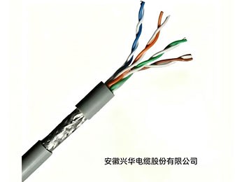
1. Product Use and Characteristics
Communication cables for coal mines are mainly used to build reliable information transmission channels between the surface and underground, as well as between various underground working points. They are a special type of cable integrating high safety (flame retardant, low smoke halogen free, explosion-proof), high reliability (environmentally resistant, anti-interference), and stable transmission performance.
2. Product Standards
GB/T3953
3. Product Classification and Designation
3.1 Product Classification
Cables are classified into unshielded and shielded types according to their structure.
3.2 Cable Type Designation
The cable type designation consists of two parts: the type code and the specification code. The types are: (MHSYV-5, MHSYVP-5).
4. Product Specifications
Cable Type | Category 5 | |
Shield Type | Unshielded | Shielded |
Nominal Conductor Diameter (mm) | 0.50 | 0.50 |
Nominal Number of Pairs | 4 | 4 |
5. Technical Requirements
5.1 Conductor
The conductor shall be a solid copper conductor. The conductor surface shall be smooth, round, free from oxidation and mechanical damage. The raw copper conductor material used shall comply with the requirements for TR type soft round copper wire in GB/T3953.
Splices in the conductor are permitted. Cold pressure welding is recommended for conductor splices. The splice area shall be smooth, flat, and free from burrs. The tensile strength of the conductor splice shall not be less than 85% of the tensile strength of an adjacent unspliced conductor of the same length.
The elongation at break of the conductor in the finished cable shall not be less than 15%. The conductor diameter and its deviation for the finished cable shall meet the requirements in the table below.
Table 2
Cable Type | Category 5 | |
Shield Type | Unshielded | Shielded |
Nominal Conductor Diameter (mm) | 0.50 | 0.50 |
Deviation (mm) | ±0.01 | ±0.01 |
5.2 Insulation
5.2.1 Insulation Material
The insulation material shall be polyolefin. The selected material shall ensure that the finished cable meets the requirements of this standard. Polyolefin insulation material shall comply with the requirements for low-density, medium-density, or high-density polyethylene as specified in YD/T760-1995.
5.2.2 Insulation Structure
The insulation structure is: — Solid polyolefin insulation;
5.2.3 Insulation Thickness
The insulation shall be continuously extruded onto the conductor. The insulation surface shall be smooth and flat. The insulation dimensions shall ensure that the finished cable meets the performance requirements specified in this standard. The maximum outer diameter of the insulation is preferably not greater than 1.5 mm.
5.2.4 Insulation Spark Test
Insulated cores shall undergo an online high-voltage spark test during the extrusion process. For cores with solid polyolefin insulation, the test voltage shall be DC 2kV to 6kV. The number of pinholes or similar defects per 12 km of insulated core shall not exceed one.
5.2.5 Insulation Color Identification Insulated cores shall use color identification markers.
The color sequence of the insulated cores shall comply with the provisions of clause 5.3.2, and the colors shall comply with GB/T6995.2.5.2.6 Insulation Mechanical and Environmental PerformanceThe mechanical and environmental performance of insulation samples taken from the finished cable shall comply with the provisions of Table 3.
Table 3 Insulation Mechanical Properties
No. | Test Item | Unit | Requirement |
1 | Insulation Color Migration Test Treatment Temperature Treatment Time | - ℃h | No migration 80±2 24 |
2 | Insulation Tensile Strength, Median HDPEMDPELDPE |
MPa |
≥16≥12≥10 |
3 | Insulation Elongation at Break, MedianSolid Polyolefin |
% |
≥300 |
4 | Insulation Shrinkage Test: Treatment TemperatureHDPE MDPELDPE Treatment Time Maximum Allowable Shrinkage | %
℃℃℃H% | 5
115±2 100±2 100±2 1 5 |
5 | Insulation Low Temperature Winding Test: (PE)Treatment Temperature Treatment Time | Failures (Specimens)℃ h | 0/10 -55±2 1 |
Note: HDPE (High Density Polyethylene); MDPE (Medium Density Polyethylene); LDPE (Low Density Polyethylene) | |||
5.3 Pair
5.3.1 Pair Structure
Formed by uniformly twisting two insulated cores of different colors, designated as a-wire and b-wire. To ensure the stability of the twisted pair structure, partial adhesion between the a-wire and b-wire insulation is permitted. The pair lay length shall be designed to enable the finished cable to meet the transmission performance requirements specified in this standard.
5.3.2 Pair Color Sequence
Insulated cores shall form pairs according to the color sequence specified in Table 4. The preferred color sequence for pairs shall also comply with Table 4.
Table 4
Pair Number | Identification Color |
1 | a | White (Blue) |
b | Blue | |
2 | a | White (Orange) |
b | Orange | |
3 | a | White (Green) |
b | Green | |
4 | a | White (Brown) |
b | Brown | |
5 | a | White (Grey) |
b | Grey | |
Note: The colors in parentheses indicate the color of the stripe or ring. | ||
5.3.2.1When the pair lay length in the cable is less than 38 mm, the pair color sequence may be indicated using the alternative color sequence shown in Table 5.Table 5
Pair Number | Identification Color | |
1 | a | White |
b | Blue | |
2 | a | White |
b | Orange | |
3 | a | White |
b | Green | |
4 | a | White |
b | Brown | |
5 | a | White |
b | Grey | |
5.3.3 Shield
5.3.3.1General
Pairs are classified as unshielded or shielded. When shielding is required for a pair, one of the methods described in clauses 5.3.3.2, 5.3.3.3, 5.3.3.4, or 5.3.3.5 shall be used. Non-hygroscopic tape of appropriate thickness may be placed inside and outside the pair shield layer.
5.3.3.2Shield consisting of one layer of single-sided laminated aluminum foil
A shield consisting of one layer of single-sided laminated aluminum foil shall meet the following requirements:
a)The single-sided laminated aluminum foil shall comply with type L requirements in YD/T723.5-2007, where the aluminum foil thickness shall not be less than 0.012 mm.
b)The single-sided laminated aluminum foil is preferably wrapped, with an overlap not less than 20%.
c)The metallic side of the single-sided laminated aluminum foil shall face outward.
5.3.3.3Shield consisting of one layer of single-sided laminated aluminum foil and one drain wire
An overall shield consisting of one layer of single-sided laminated aluminum foil and one drain wire shall meet the following requirements:
a)The single-sided laminated aluminum foil shall comply with type L requirements in YD/T723.5-2007, where the aluminum foil thickness shall not be less than 0.012 mm.
b)The single-sided laminated aluminum foil is preferably wrapped, with an overlap not less than 20%.
c)The drain wire shall be a tinned round copper wire with a nominal diameter not less than 0.5 mm and shall comply with type TXRH requirements in GB/T4910.
d)The metallic side of the single-sided laminated aluminum foil shall face inward and be in electrical contact with the drain wire.
5.3.3.4Shield consisting of one braided layer
A shield consisting of one braided layer shall meet the following requirements:
a)The braid shall use tinned round copper wire complying with type TXRH in GB/T4910 or TR soft round copper wire in GB/T3953.
b)A single broken wire in one direction in the braid is permitted, with a length not exceeding 150 mm. The broken ends shall be trimmed neatly.
c)The fill factor of the braid shall not be less than 0.41, or the braid density shall not be less than 65%.
5.3.3.5Shield consisting of one layer of single-sided laminated aluminum foil and one braided layer
A shield consisting of one layer of single-sided laminated aluminum foil and one braided layer shall meet the following requirements:
a)The metallic side of the single-sided laminated aluminum foil shall face outward and be in electrical contact with the braided layer.
b)The single-sided laminated aluminum foil shall comply with type L requirements in YD/T723.5-2007, where the aluminum foil thickness shall not be less than 0.012 mm.
c)The single-sided laminated aluminum foil is preferably wrapped, with an overlap not less than 20%.
d)The braid shall use tinned round copper wire complying with type TXRH in GB/T4910.
e)A single broken wire in one direction in the braid is permitted, with a length not exceeding 150 mm. The broken ends shall be trimmed neatly.
f)The fill factor of the braid shall not be less than 0.16, or the braid density shall not be less than 30%.
5.4 Subunit
5.4.1Each subunit of the cable should preferably be formed by twisting 4 pairs. The pairs within each subunit shall be of the same type.
5.4.2The pairs in each subunit should preferably use the color sequence of pairs 1 to 4 from Table 4 or Table 5, or they may sequentially use the color sequences specified in Table 4 or Table 5.
5.5 Core
5.5.1 Core Arrangement
The cable core arrangement shall comply with the following requirements:
a)The core may be formed by stranding several subunits together, or by concentrically stranding multiple pairs.
b)Insulated spacers or fillers may be placed in the core to stabilize the transmission characteristics of the cable.
c)The color sequence of cable pairs shall comply with Table 4 or Table 5. The core stranding lay length shall be designed to enable the finished cable to meet the transmission performance requirements specified in this standard.
d)The recommended core arrangement is given in Appendix A. For cables formed by stranding subunits, the color sequence of subunit binding tapes shall comply with clause 5.4.3. Viewed from the A end of the cable, the pair numbers within each subunit shall be arranged sequentially in a clockwise direction, and subunit numbers shall be arranged sequentially from the inside out in a clockwise direction. For concentrically stranded cables, the pair color sequence shall comply with clause 5.3.2; viewed from the A end of the cable, pair numbers shall be arranged sequentially from the inside out in a clockwise direction.
e)Upon user request, the cable core may contain both subunits consisting of shielded pairs and subunits consisting of unshielded pairs.
5.5.2 Core Taping
One or more layers of non-hygroscopic tape of appropriate thickness may be applied over the core.
5.5.3 Overall Shield
The cable may or may not have an overall shield.
When an overall shield is required, one of the methods described in clauses 5.3.3.2, 5.3.3.3, 5.4.3.4, or 5.3.3.5 should be used. Non-hygroscopic tape of appropriate thickness shall be placed inside the overall shield.
5.6 Sheath
5.6.1 Sheath Material
The sheath material shall be polyvinyl chloride (PVC). The selected material shall ensure that the finished cable meets the requirements of this standard. PVC sheath material shall comply with H-70 requirements in GB/T8815;
5.6.2 Sheath Integrity
The sheath shall be applied continuously and uniformly over the core. The surface shall be smooth, flat, round, free from holes, cracks, bubbles, and other defects.
5.6.3 Minimum Sheath Thickness
The minimum sheath thickness on the finished cable shall comply with Table 6.
Table 6 Minimum Thickness of PVC Sheath
Core Diameter Range (mm) | Minimum Average Sheath Thickness (mm) | Minimum Sheath Thickness (mm) |
3.4~8.8 | 1.20 | 1.00 |
5.6.4 Maximum Cable Outer Diameter
The maximum outer diameter of the finished cable shall comply with Table 7.
Table 7 Maximum Cable Outer Diameter
Nominal Number of Pairs | Cable Category | Shield Type | Maximum Cable Outer Diameter (mm) |
4 | Category 5 | Unshielded | 7.8 |
Category 5 | Shielded | 8.2 |
5.6.5Non-hygroscopic non-metallic rip cords may be placed under the sheath upon user request.
5.6.6The sheath color is generally blue, but other colors may also be produced upon user request.
5.7 Cable Manufacturing Length
The nominal manufacturing length of the cable shall be integer multiples of 100 m to 110 m.
5.8Mechanical, Environmental, and Safety Performance of the Cable100Ω In addition to the relevant clauses above, the mechanical, environmental, and safety performance of the finished cable shall also comply with Table 8.

Table 8 Mechanical, Environmental, and Safety Performance of Cable
No. |
Test Item |
Unit |
Requirement | Treatment Temperature ℃ | Treatment Time h |
1 | Mechanical Properties | ||||
1.1 | Sheath Elongation at Break (Median) | % | ≥150 |
23±5 |
16 |
1.2 | Sheath Tensile Strength (Median) | % | ≥13.5 | ||
2 | Environmental Performance | ||||
2.1 | Sheath Elongation Median After Aging | ||||
Elongation at Break | ≥125 |
100±2 |
24×7 | ||
Change in Elongation at Break | -20~+20 | ||||
2.2 | Sheath Elongation Median After Aging | ||||
Tensile Strength | ≥12.5 |
100±2 |
24×7 | ||
Change in Tensile Strength | -20~+20 | ||||
2.3 | Cable Low Temperature Winding Test | Mandrel diameter: 8 times cable outer diameter | No cracking | -20±1 | 4 |
2.4 | Thermal Shock Test | No cracking | 150±1 | 1 | |
3 | Safety Performance | ||||
3.1 | Single Cable Vertical Flame Spread Test | Distance between lower edge of upper support and carbonized part | - | ||
starting point from the lower edge of the upper support | shall not exceed 50 mm The downward extension of combustion shall not exceed 540 mm below the lower edge of the upper support. | ||||
3.2 | Vertical flame spread test for bunched wires or cables | Maximum carbonization range shall not be higher than 2.5 m from the bottom edge of the burner. |
- | ||
aThe formula for change in elongation at break is: Change in elongation at break=(Elongation before aging-Elongation after aging)/Elongation before aging×100%.bThe formula for change in tensile strength is: Change in tensile strength=(Tensile strength before aging-Tensile strength after aging)/Tensile strength before aging×100%. | |||||
5.9 Electrical Performance
The electrical performance of 100Ω cables shall comply with Table 9.
Table 9 Electrical Performance of 100Ω Cable at 20℃
No. | Test Item | Unit | Requirement | Length Conversion | ||
1 | Single Conductor DC Resistance | Category 5 | Ω/100m | ≤9.5 | Measured value/La | |
2 |
DC Resistance Unbalance | Between conductors within a pair | % | ≤2.0 | - | |
Between pairs | ≤4.0 | - | ||||
3 | Dielectric Strengthb,DC,or |
kV | 1min | 2s | - | |
Between conductors | 1.0 | 2.5 | - | |||
Conductor to screenc | 2.5 | 6.3 | - | |||
4 | Minimum Insulation Resistance20℃,DC100~500V | MΩ·km |
Measured value×L×0.1 | |||
Insulation resistance of each insulated conductor to the remaining conductors and screen | ≥5000 | |||||
5 | Capacitance,1kHz, maximum | nF/100m | ≤5.6 | Measured value/L | ||
6 | Pair-to-ground capacitance unbalance,1kHz, maximumc | pF/100m | 120 | Measured value/L | ||
7 | Transfer Impedancec, maximum | - | ||||
Frequency1MHz (Category 5) Frequency10MHz (Category 5) Frequency30MHz (Category 5) Frequency100MHz (Category 5) |
mΩ/m | ≤50≤100≤300≤1000 |
- | |||
8 | Coupling Attenuationc, minimum | - | ||||
5类 | Not required | - | ||||
5e | 30MHz~100MHz | dB | ≥55 | - | ||
9 | Insulated core breaks and shorts | - | No breaks, no shorts | - | ||
10 | Screen Continuityd | Electrically continuous | - | |||
Notes: a In the table, L is the actual length of the cable, in units of 100 m. bAC voltage may be used for testing; its value is the DC voltage divided by 1.5. cTransfer impedance, coupling attenuation, and screen continuity tests are only applicable to shielded cables.dWhen the cable does not have a screen, this test is not performed. | ||||||
5.10 Transmission Performance
5.10.1 Phase Delay
20℃100Ω5Category, from 4 MHz to the maximum transmission frequency specified for the cable category, the phase delay of any pair in the cable shall not exceed the values calculated by the formula.
Typical values of phase delay and propagation velocity at specific frequencies are given in Table 10.
Table 10 Typical Values of Phase Delay and Propagation Velocity
Frequency MHz | Maximum Phase Delayns/100m |
Minimum Propagation Velocitym/s |
5Category | ||
4 | 552 | 0.604C |
8 | 547 | 0.610C |
10 | 545 | 0.612C |
16 | 543 | 0.614C |
20 | 542 | 0.615C |
25 | 541 | 0.616C |
31.25 | 540 | 0.617C |
62.5 | 539 | 0.619C |
100 | 538 | 0.620C |
Note: C is the propagation velocity of electromagnetic waves in a vacuum, C=299, 792, 458m/s | ||
5.10.2 Delay Skew
For Category 5 cables, from 4 MHz to the maximum transmission frequency specified for the cable category, the maximum delay skew between any two pairs in the cable shall not exceed 40 ns/100m.
5.10.3 Attenuation
Measured at or corrected to 20℃. From 4 MHz to the maximum transmission frequency specified for the cable category, the attenuation value of any pair shall not exceed the value determined by the formula in Table 11.
Table 11 Attenuation
Cable Category | Frequency MHz | AttenuationdB/100m |
Category 5 | 4~100 | s1.967,/F+0.023f+0.05/、JF |
Due to environmental temperature effects, the attenuation temperature coefficient shall be taken from Table 12. In case of dispute, attenuation shall be measured at 20℃ ± 1℃.
Table 12 Attenuation Temperature Coefficient
Test Item | Attenuation Temperature Coefficient | ||
Ambient Temperature Range | <20℃ | 20~40℃ | 40~60℃ |
Unshielded Cable | 0.002/℃ | 0.004/℃ | 0.006/℃ |
Shielded Cable | 0.002/℃ | 0.002/℃ | 0.002/℃ |
5.10.4 Near End Crosstalk
5.10.4.1100Ω Cable Near End Crosstalk Attenuation (NEXT)
From 4 MHz to the maximum transmission frequency specified for the cable category, the near end crosstalk attenuation (NEXT) of all pair combinations in the cable shall not be less than the value determined by the formula in Table 13. When the calculated value exceeds 78 dB, the corresponding minimum requirement shall be taken as 78 dB.
Table 13 Near End Crosstalk Attenuation (NEXT) for 100Ω Cable
Cable Category | Frequency MHz | Minimum Near End Crosstalk Attenuation (dB)dB/100m |
Category 5 | 4~100 | NEXT≥62.3-15lg(f) |
5.10.4.2Near End Crosstalk (NEXT) and Power Sum Near End Crosstalk (PSNEXT) for Multi-subunit Cables
For large pair count cables consisting of multiple subunits or pairs, the near end crosstalk attenuation (NEXT) of all pair combinations and the power sum near end crosstalk (PSNEXT) for any pair, from 4 MHz to the maximum transmission frequency specified for the cable category, shall not be less than the value determined by the formula in clause 5.10.4.
5.10.5 Far End Crosstalk
5.10.5.1 Equal Level Far End Crosstalk Attenuation (ELFEXT) for 100Ω Cable
From 4 MHz to the maximum transmission frequency specified for the cable category, the equal level far end crosstalk attenuation of any pair combination shall not be less than the value determined by the formula in Table 14. When the calculated value exceeds 78 dB, the corresponding minimum requirement shall be taken as 78 dB.
Table 14 Equal Level Far End Crosstalk Attenuation (ELFEXT) for 100Ω Cable
Cable Category | Frequency f MHz | Equal Level Far End Crosstalk Attenuation dBdB/100m |
Category 5 | 4~100 | ELFEXT≥60-20lg(f) |
5.10.6 Characteristic Impedance (Zc)
5.10.6.15Category Cable Characteristic Impedance Requirements
The characteristic impedance (Zc) of each pair, from 4 MHz to the maximum transmission frequency specified for the cable category, shall comply with Table 15. If the characteristic impedance meets the requirements of this clause, then measurement of return loss (RL) in clause 5.10.7 is not required.
Table 15 Characteristic Impedance (Zc)
Cable Category | Frequency f (MHz) | Characteristic Impedance (Ω) |
Category 5 | 4~100 | 100±15 |
5.10.7 Return Loss (RL)
Return loss (RL) measurement is performed only if the characteristic impedance (Zc) does not meet the requirements of clause 5.10.6.
From 4 MHz to the maximum transmission frequency specified for the cable category, the return loss of each pair shall not be less than the value determined by the formula in Table 16.
Table 16 Return Loss (RL) for 100Ω Cable
Cable Category | Frequency Range (MHz) Requirements | Return Loss (RL), Minimum |
Category 5 | 1≤f≤10 | RL≥17+3lg(f) |
10<f≤20 | RL≥20 | |
20<f≤100 | RL≥20-7lg(f/20) |
5.10.8 Unbalance Attenuation
The unbalance attenuation test consists of two parts: transverse conversion loss (TCL) and equal level transverse conversion transfer loss (ELTCTL).
5.10.8.1Transverse Conversion Loss (TCL)
From 1 MHz to the frequency range given in Table 20, the transverse conversion loss (TCL) of any pair shall not be less than the value determined by the formula in Table 17.
Table 17 Transverse Conversion Loss (TCL)
Cable Category | Frequency f (MHz) | Transverse Conversion Loss (TCL), Minimum (dB) |
Category 5 | 1~100 | TCL≥50-10lg(f) |
5.10.8.2Equal Level Transverse Conversion Transfer Loss (ELTCTL)
From 1 MHz to the frequency range given in Table 18, the equal level transverse conversion transfer loss (ELTCTL) of any pair shall not be less than the value determined by the formula in Table 19.
Table 18 Equal Level Transverse Conversion Transfer Loss (ELTCTL)
Cable Category | Frequency f (MHz) | Equal Level Transverse Conversion Transfer Loss (ELTCTL), Minimum (dB) |
Category 5 | 1~30 | ELTCTL≥35-20lg(f) |
6 Test Methods
6.1 General
When performing electrical and transmission performance tests on the cable, unless otherwise specified, the cable length shall not be less than 100 m.
For measurements of coupling attenuation, phase delay, attenuation, unbalance attenuation, near end crosstalk or power sum near end crosstalk, equal level far end crosstalk or power sum equal level far end crosstalk, characteristic impedance, and return loss, swept frequency measurements with linear or logarithmic frequency intervals shall be used. The number of frequency points for near end crosstalk and far end crosstalk measurements shall be at least 200 times the number of octaves in the specified frequency range. For other parameters, it shall be at least 100 times the number of decades in the specified frequency range.
When measuring cable on its original packaging, the measured values of capacitance, characteristic impedance, attenuation, and crosstalk may sometimes deviate by up to 10% from actual values due to tight packaging and winding effects. In case of dispute, measurements of capacitance, characteristic impedance, attenuation, and crosstalk shall be performed after removing the cable sample from packaging and laying it out. The cable sample shall be placed on a non-metallic work surface or ground, maintaining a distance of at least 25 mm from conductive equipment or lines.
6.2 Structural Test Methods
6.2.1 Color Sequence and Shield Structure
Color sequence and shield structure shall be checked visually.
6.2.2 Conductor Diameter and Insulation Outer Diameter
Conductor diameter measurement shall be conducted according to GB/T4909.2-2009; insulation outer diameter measurement shall be conducted according to clause 8.1 of GB/T2951.11-2008.
6.2.3 Insulation Color and Color Migration
Insulation color and color migration test shall be conducted according to YD/T837.3-1996.
6.2.4 Thickness of Single-sided Laminated Aluminum Foil
The thickness of the single-sided laminated aluminum foil shall be measured using a micrometer or thickness gauge with an accuracy of no less than 0.002 mm.
6.2.5 Overlap Rate of Single-sided Laminated Aluminum Foil
The overlap rate of the single-sided laminated aluminum foil shall be measured on the finished cable using a steel tape measure with a resolution of no less than 0.5 mm.
6.2.6 Braid Fill Factor
Braid fill factor measurement shall be conducted according to GB/T17737.1-2000.
6.2.7 Minimum Cable Sheath Thickness and Maximum Outer Diameter
Measurement of minimum and maximum cable sheath diameter shall be conducted according to GB/T2951.11-2008. The equivalent outer diameter of a non-circular cable equals the measured actual circumference of the sheath divided by π.
6.2.8 Sheath Appearance
Sheath appearance shall be checked visually.
6.3 Mechanical Performance Test Methods
6.3.1 Conductor Elongation at Break
Conductor elongation at break test shall be conducted according to GB/T4909.2-2009.
6.3.2 Insulation Tensile Strength and Elongation at Break
Insulation tensile strength and elongation at break shall be conducted according to GB/T2951.11-2008. The tensile speed for HDPE and PP test pieces is (250 ± 50) mm/min. In case of dispute, the tensile speed shall be (25 ± 5) mm/min.
6.3.3 Sheath Tensile Strength and Elongation at Break
Sheath tensile strength and elongation at break shall be conducted according to GB/T2951.11-2008. The minimum thickness of PVC and LSNHP sheath test pieces is 0.4 mm. For LSNHP sheath test pieces, the tensile speed may be (250 ± 50) mm/min. In case of dispute, the tensile speed shall be (25 ± 5) mm/min.
6.4 Environmental Performance Test Methods
6.4.1 Insulation Shrinkage Test
Insulation shrinkage test shall be conducted according to GB/T2951.13-2008.
6.4.2 Insulation Low Temperature Winding Test
Insulation low temperature winding test shall be conducted according to GB/T2951.14-2008.
6.4.3 Sheath Tensile Strength and Elongation at Break After Aging
Sheath tensile strength and elongation at break after aging test shall be conducted according to GB/T2951.11-2008. The minimum thickness of PVC, LSZH, and PE test pieces is 0.4 mm. The tensile speed for sheath test pieces may be (250 ± 50) mm/min. In case of dispute, the tensile speed shall be (25 ± 5) mm/min.
6.4.4 Cable Low Temperature Winding Test
Cable low temperature winding test shall be conducted according to GB/T2951.14-2008.
6.4.5 Cable Low Temperature Impact Test
Cable low temperature impact test shall be conducted according to GB/T2951.14-2008.
6.4.6 Thermal Shock Test
Thermal shock test shall be conducted according to GB/T2951.31-2008.
6.5 Flame Retardant Performance Test Methods
6.5.1 Single Cable Vertical Test
Single cable vertical test shall be conducted according to clause 4.2 of MT/T386.
6.5.2 Bunched Combustion Test
Conducted according to clause 4.3 of MT/T386.
6.6 Electrical and Transmission Performance Test Methods
For transmission performance items in routine inspection, testing may be performed from one end of the product packaging box or reel.
In type testing, for near end crosstalk, characteristic impedance, and return loss, test cable samples shall be taken from the product packaging box or reel. The sample length shall be not less than 100 m, and the cable sample shall be laid out for two-end testing. Only after passing the two-end test can the sample be deemed to have passed the type test. Electrical and transmission performance test methods are given in Table 19.
Table 19 Electrical and Transmission Performance Test Methods
No. | Test Item | Clause in this Standard | Test Method | |
1 Electrical Performance | ||||
1.1 | Single Conductor DC Resistance | Table 9, No. 1 | YD/T838.2 | |
1.2 |
DC Resistance Unbalance | Between conductors within a pair |
Table 9, No. 2 |
YD/T838.2 |
Between pairs | ||||
1.3 | Dielectric Strength | Table 9, No. 3 | YD/T837.2 | |
1.4 | Insulation Resistance | Table 9, No. 4 | YD/T837.2 | |
1.5 | Capacitance | Table 9, No. 5 | YD/T837.2 | |
1.6 | Pair-to-ground Capacitance Unbalance | Table 9, No. 6 | YD/T837.2 | |
1.7 | Insulated Core Breaks and Shorts | Table 9, No. 9 | Multimeter continuity | |
1.8 | Screen Continuity | Table 10, No. 10 | Multimeter continuity | |
2 | Transmission Performance | |||
2.1 | Phase Delay | 5.10.1 | IEC 61156-1 | |
2.2 | Delay Skew | 5.10.2 | IEC 61156-1 | |
2.3 | Attenuation | 5.10.3 | YD/T838.1 | |
2.4 |
Near End Crosstalk | Near End Crosstalk Attenuation | 5.10.4.1 | YD/T838.1 |
Power Sum Near End Crosstalk Attenuation | 5.10.4.2 | YD/T838.1 | ||
2.5 |
Unbalance Attenuation | Transverse Conversion Loss | 5.10.8.1 | YD/T838.1 |
Equal Level Transverse Conversion Transfer Loss | 5.10.8.2 | YD/T838.1 | ||
2.6 | Far End Crosstalk | Equal Level Far End Crosstalk Attenuation | 5.10.5.1 | YD/T838.1 |
2.7 | Characteristic Impedance | 5.10.6.1 | YD/T1019-2013 Appendix B | |
2.8 | Return Loss | 5.10.7 | YD/T1019-2013 Appendix B | |
7 Inspection Rules
7.1 Inspection Classification
Cables must be inspected by the manufacturer's quality inspection department before leaving the factory. Only cables that pass inspection may be shipped. Each shipment shall be accompanied by a quality inspection certificate. Inspection is divided into routine inspection and type inspection.
7.2 Routine Inspection
7.2.1 Routine inspection items are divided into full inspection and sampling inspection. Full inspection items are performed on each reel of finished cable, as shown in Table 20.
Table 20
No. | Test Item | Clause in this Standard |
1 | Dimensions and Structure | |
1.1 | Conductor Diameter | 5.1 |
1.2 | Color Sequence | 5.3.2 |
1.3 | Shield Structure | 5.5.3 |
1.4 | Sheath Surface | 5.6.2 |
1.5 | Sheath Thickness | 5.6.3 |
1.6 | Identification Marking and Length Marking | 8.1 |
2 | Electrical Characteristics | |
2.1 | Single Conductor DC Resistance | Table 9, No. 1 |
2.2 | Pair DC Resistance Unbalance | Table 9, No. 2 |
2.3 | Dielectric Strength | Table 9, No. 3 |
2.4 | Insulation Resistance | Table 9, No. 4 |
2.5 | Insulated Core Breaks and Shorts | Table 9, No. 9 |
2.6 | Screen Continuity | Table 9, No. 10 |
3 | Transmission Performance | |
3.1 | Attenuation | 5.10.3 |
3.2 | Near End Crosstalk and Power Sum Near End Crosstalk Attenuation | 5.10.4 |
3.3 | Equal Level Far End Crosstalk Attenuation and Power Sum Equal Level Far End Crosstalk Attenuation | 5.10.5 |
4 | Flame Retardant Performance | |
4.1 | Single Cable Vertical Test | 6.5.1 |
7.2.2 Sampling inspection shall be performed randomly from each inspection batch. Sampling inspection items are specified in Table 21.
Table 21 Routine Sampling Inspection Items
No. | Test Item | Clause in this Standard |
1 | Capacitance | Table 9, No. 5 |
2 | Pair-to-ground Capacitance Unbalance | Table 9, No. 6 |
3 | Phase Delay | 5.10.1 |
4 | Delay Skew | 5.10.2 |
5 | Characteristic Impedance | 5.10.6 |
6 | Return Loss | 5.10.7 |
7.3.2 Type Inspection
Type testing is a full performance inspection of the product, including routine inspection items (Table 20) and sampling inspection items (Table 21). Type test items shall comply with Table 22.
Table 22 Type Test Items
No. | Test Item | Clause in this Standard |
1 | Dimensions and Structure | |
1.1 | Color Sequence and Shield Structure | 5.1, 5.3.2, 5.3.3.1 |
1.2 | Conductor Diameter | 5.1, Table 2 |
1.3 | Insulation Outer Diameter | 5.2.3 |
1.4 | Insulation Color and Migration | 5.2.6, Table 3 |
1.5 | Thickness of Single-sided Laminated Aluminum Foil | 5.3.3.2 |
1.6 | Overlap Rate of Single-sided Laminated Aluminum Foil | 5.3.3.2 |
1.7 | Braid Fill Factor | 5.3.3.4 |
1.8 | Minimum Cable Sheath Thickness and Maximum Outer Diameter | 5.6.3, Table 6 / 5.6.4, Table 7 |
1.9 | Sheath Surface | 5.6.2 |
1.10 | Identification Marking and Length Marking | 8.1 |
2 | Mechanical Properties | |
2.1 | Conductor Elongation at Break | 5.1 |
2.2 | Insulation Tensile Strength and Elongation at Break | 5.2.6, Table 3 |
2.3 | Sheath Tensile Strength and Elongation at Break | 5.8, Table 8 |
3 | Environmental Tests | |
3.1 | Insulation Shrinkage | 5.2.6, Table 3 |
3.2 | Insulation Low Temperature Winding | 5.2.6, Table 3 |
3.3 | Sheath Tensile Strength and Elongation at Break After Aging | 5.8, Table 8 |
3.4 | Cable Low Temperature Winding | 5.8, Table 8 |
3.5 | Thermal Shock | 5.8, Table 8 |
4 | Safety Performance | |
4.1 | Single Cable Vertical Test | 6.5.1 |
4.2 | Category C Bunched Combustion Test | 6.5.2 |
5 | Electrical Performance | |
5.1 | Single Conductor DC Resistance | Table 9, No. 1 |
5.2 | DC Resistance Unbalance | Table 9, No. 2 |
5.3 | Dielectric Strength | Table 9, No. 3 |
5.4 | Insulation Resistance | Table 9, No. 4 | |
5.5 | Capacitance | Table 9, No. 5 | |
5.6 | Pair-to-ground Capacitance Unbalance | Table 9, No. 6 | |
5.7 | Insulated Core Breaks and Shorts | Table 9, No. 9 | |
5.8 | Screen Continuity | Table 9, No. 10 | |
6 | Transmission Performance | ||
6.1 | Phase Delay | 5.10.1 | |
6.2 | Delay Skew | 5.10.2 | |
6.3 | Attenuation | 5.10.3 | |
6.4 |
Near End Crosstalk | Near End Crosstalk Attenuation | 5.10.4.1 |
Power Sum Near End Crosstalk Attenuation | 5.10.4.2 | ||
6.5 |
Unbalance Attenuation | Transverse Conversion Loss | 5.10.8.1 |
Equal Level Transverse Conversion Transfer Loss | 5.10.8.2 | ||
6.6 | Far End Crosstalk | Equal Level Far End Crosstalk Attenuation | 5.10.5.1 |
6.7 | Characteristic Impedance | 5.10.6.1 | |
6.8 | Return Loss | 5.10.7 | |
Under normal production conditions, type testing shall be conducted once a year. Type testing shall also be conducted under any of the following circumstances:
a)When new products or old products transferred to a new factory are undergoing type test verification;
b)When there are significant changes in structure, materials, or processes after formal production that may affect product performance;
c)When routine inspection results differ significantly from the previous type test;
d)When there is a dispute over product quality between the supplier and buyer requiring arbitration;
e)When the national quality supervision authority requests type testing.
7.3.3 Sampling
Samples for type testing shall be randomly selected from cables that have passed routine inspection. The sample size for each cable type is 3 reels, and the sample must include the maximum nominal number of pairs for that type.
7.3.4 Judgment Rules
If any single indicator in the type test fails, double the number of samples from the same batch may be taken for re-testing of the failed item. If it still fails, the type test for that cycle is judged as non-conforming.
If the type test fails, the product shall immediately cease routine inspection. After identifying the cause and implementing corrective measures, type testing must be conducted again. Only after passing can formal production resume.
8 Marking, Packaging, Transport, and Storage
8.1 Marking
8.1.1 Identification Marking
The outer surface of the cable sheath shall be printed with the manufacturer's name or code, year of manufacture, cable type, product standard, and mine product safety mark. The spacing shall not exceed 1 m. The marking on the finished cable shall comply with GB/T6995.3-2008. The mine safety mark shall comply with clause 4.1 of AQ1043.
8.1.2 Length Marking
The outer surface of the cable sheath shall have permanently identifiable clear length markings, in blue (or other colors as requested by the user). Length markings are in meters, with a marking interval of 1 m. The length marking error shall not exceed ±0.5%.8.1.3 End Identification Marking
End A of the cable is marked in red, and End B is marked in green.
8.2 Packaging Marking
Each coil or reel shall be provided with a label indicating the following:
1Manufacturer's name or code and registered trademark;
2Product type and specification;
3Length (m) and weight (kg)
4Date of manufacture or production batch number;
5Mine product safety mark
9 Packaging, Transport, Storage, and Installation
9.1 Packaging
9.1.1The cable shall be delivered in coils or on reels. The bending radius shall not be less than the value specified in clause 5.13.3 of this standard. Both ends of the cable must be sealed. Coiled or reeled cable shall be properly packaged.
9.1.2The weight of coil-packaged cable shall not exceed 50 kg.
9.1.3Cables in coils or on reels shall be wound neatly and properly packaged. Cable reels shall comply with JB/T8137. The reel shall indicate the correct direction of rotation.
9.1.4Each coil or reel shall be provided with a label indicating the marking content specified in 8.2.
9.2 Transport and Storage
The cable shall be suitable for all modes of transport including water, land, and air.During transport and storage, the following precautions should be taken:
(1) Prevent moisture ingress into the cable;
(2) Prevent severe bending and other mechanical damage;
(3) Prevent exposure to high temperatures and direct sunlight.
9.3 Installation
Cable installation temperature range: -20℃ ~ +60℃. The minimum bending radius during installation of 100Ω cables shall not be less than 8 times the cable outer diameter.
If you are interested in our products, or want to ask related questions, please leave a message to us.
We will reply and serve you as soon as possible. Thank you for visiting our official website.