
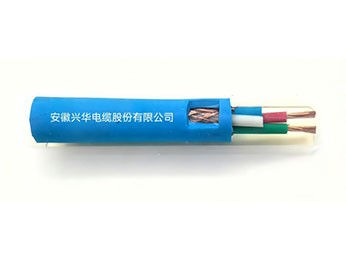
I. ProductApplication and Features
Coal Mine Polyethylene Insulated Braided Shielded PVC Sheathed Communication CableMainly used for underground backbone communication lines, monitoring and sensing systems, and signal transmission of automation control systems. It is a general-purpose coal mine communication cable with reliable performance, economical cost, suitable for fixed installation, and serves as the foundation for building underground communication networks.。
II. Product Standards
GB/T 2900.10
III. Product Modelsand Names
Name | Model | Specification |
Coal Mine Polyethylene Insulated Braided ShieldedPVC Sheathed Communication Cable |
MHYVP | 2 × 3.3mm2+2×0.85mm2 |
2 × 3.3mm2+2×0.85mm2+2×0.35mm2 |
Table1
IV. Product Specifications
Number of Cores× Nominal Conductor Cross-Sectional Area (mm2) | Conductor Cross-Section mm2 | Nominal Insulation Thickness mm | Nominal Sheath Thickness mm | Maximum Cable Outer Diameter mm |
2×3.3+2×0.85 | 3.3 | 0.80 |
1.6 |
17.0 |
0.85 | 0.50 | |||
2×3.3+2×0.85+2×0.35 | 3.3 | 0.80 |
1.6 |
19.0 |
0.85 | 0.60 | |||
0.35 | 0.40 |
Table2
V. Technical Requirements
5.1 Conductor
5.1.1 The conductor shall be a stranded conductor, and the single wire in the conductor may be tinned or untinned round copper wire. Soft round copper wireshall comply withGB/T3953, and tinned soft round copper wire shall comply withGB/T4910. The DC resistance of the drain wire at 20°C shall not exceed95.0Ω/km。
5.1.2 The conductor structure shall comply with the requirements of Table 3. The single wire in the conductor may be tinned or untinned round copper wire. The surface shall be smooth,free of oil stains, without protrusions or other defects that may damage the insulation.
Table3 Conductor Structure
Nominal Cross-Sectionmm2 | Conductor Structure | Maximum Conductor Resistance at 20°C Ω/Km | |
Number of Single Wires/Single Wire Diameter | Copper Conductor | Tinned Copper Conductor | |
0.35 | 7/0.25 | 61.2 | 64.0 |
0.85 | 7/0.40 | 22.9 | 23.3 |
3.3 | 19/0.47 | 6.59 | 6.72 |
5.2 Insulation
5.2.1 The insulation shall be made of polyethylene cable compound.
5.2.2 The insulation shall be tightly extruded onto the conductor and shall be easily strippable without damaging the conductor. The insulation surface shall be smooth, with uniform color, and shall be free of cracks and other damage.
5.2.3 The nominal insulation thickness shall comply with the requirements of Table 2.
5.2.4 The average insulation thickness shall be not less than the nominal value, and the thinnest point shall be not less than 90% of the nominal value minus 0.05 mm.
5.3 Insulation Performance Requirements
5.3.1 The insulated core shall withstand the AC 50 Hz spark test specified in GB/T 3048.9 as an intermediate inspection. The test voltage shall comply with the requirements of Table 4.
Table4
No. | Nominal Insulation Thicknessδmm | Spark Test Voltagekv |
1 | δ≤0.5 | 5 |
2 | 0.5<δ≤1.0 | 6 |
5.3.2 The mechanical properties of the cable insulation shall comply with the requirements of Table 5.
5.3.3 The insulation resistance of the insulated core at 20°C shall be not less than 5000 MΩ·km.
5.4 Insulated Core Identification and Wire Pairs
Table5
No. | Item | Technical Performance |
1 | Tensile Strength/MPaElongation at Break% | ≥10.0≥300 |
5.4.1 For cores with 19/0.47 conductor, the insulation colors shall be one red and one orange each (power core). For cores with 7/0.40 conductor, the insulation colors shall be one yellow and one brown (signal core). For cores with 7/0.25 conductor, the insulation colors shall be one white and one black (signal core). Insulated core colors can also be produced according to customer requirements.
5.5 Cable Core
5.5.1 Cable Core of Four-Core Cable
5.5.1.1 The cable core of the four-core cable shall be formed by stranding four insulated cores of red, orange, yellow, and brown colors. The lay length shall not exceed 20 times. The stranding direction of the cable core shall be right-hand.
5.5.1.2 A layer of aluminum-plastic composite tape shall be wrapped around the yellow insulated core as required, with an overlap width of not less than 20% of the tape width.
5.5.2 Cable Core of Six-Core Cable
5.5.2.1 The cable core of the six-core cable shall be formed by stranding four insulated cores of red, orange, yellow, and brown colors, as well as a black-and-white insulated wire pair. The lay length shall not exceed 20 times. The stranding direction of the cable core shall be right-hand.
5.5.2.2 A layer of aluminum-plastic composite tape shall be wrapped around the yellow insulated core as required. The black and white insulated cores shall be stranded and then overlapped with a layer of aluminum-plastic composite tape, with an overlap width of not less than 20% of the tape width.
5.5.2.3 The gaps in the cable core may be filled with non-hygroscopic materials.
5.6 Wrapping Tape
5.6.1 The outside of the cable core shall be overlapped or longitudinally wrapped with non-hygroscopic and non-oil-absorbing insulating tape. The wrapping tape shall be tightly bound, with an overlap of not less than 20% of the tape width, and not less than 3 mm at minimum.
5.7 Inner Sheath
5.7.1 The inner sheath shall be made of polyvinyl chloride (PVC) sheath compound.
5.7.2 The inner sheath shall be tightly extruded onto the cable core or insulating tape, and shall be easily strippable without damaging the insulation or insulating tape. The inner sheath shall be smooth, without cracks andother mechanical damage.
5.7.3 The nominal thickness of the inner sheath is 1.2 mm, with a negative tolerance of 20% allowed.
5.7.4 The inner sheath performance of the cable shall comply with the requirements of Item 1 and Item 2 in Table 6.
Table 6 Main Properties of PVC Sheath
No. | Item | Technical Performance | |
1 | Mechanical Properties Tensile StrengthMPaElongation at Break% |
≥12.5≥150 | |
2 | Mechanical Properties After Aging Treatment Conditions: Temperature℃ TimedTensile StrengthN/mm2 Tensile Strength Change Rate%Elongation at Break% Elongation at Break Change Rate% |
80±2 7 ≥12.5≤±25≥150≤±25 | |
3 | High Temperature Pressure Test Test Temperature℃Indentation Depth% |
80±2≤50 | |
4 | Low Temperature Performance Test Low Temperature Impact Test Test Temperature-15℃(Deviation±2℃)Low Temperature Winding Test Test Temperature-15℃(Deviation±2℃)Low Temperature Tensile Test Test Temperature-15℃(Deviation±2℃) |
No Cracking
No Cracking
≥20 | |
5 | Crack Resistance Test Temperature Duration |
150℃(Deviation±3℃)1h |
No Cracking |
5.8 Shield Layer
5.8.1 The cable shield shall adopt a structure of aluminum-plastic composite tape plus copper wire braiding.
5.9 Braided Shield
5.9.1 A round copper wire braided shield shall be used outside the inner sheath of the MHYVP type cable. The round copper wire shall comply with the provisions of GB 3953. The braiding density shall be not less than 80%. The diameter of the round copper wire used for braiding shall be not less than 0.15 mm.
5.9.2 The shield layer shall not be spliced as a whole, and the exposed copper wire ends shall be trimmed. One metal wire spool replacement is permitted per 1 meter of length.
5.9.3 The braiding density (K) is expressed as a percentage.
5.10 Outer Sheath
5.10.1 The outer sheath shall be blue. It shall be made of polyvinyl chloride (PVC) cable compound, and its properties shall comply with the provisions of GB/T 8815.
5.10.2 The outer sheath shall be tightly extruded over the cable core, shield layer, or steel wire armor layer, and shall be easily strippable without damaging the insulation, inner sheath, shield layer, or steel wire galvanizing layer. The outer sheath surface shall be smooth, with uniform color, free of cracks, bubbles, inclusions, or other mechanical damage.
5.10.3 The nominal thickness of the outer sheath shall comply with the provisions in Table 2.
5.10.4 The average thickness value of the outer sheath shall be not less than the specified nominal value, and the thickness at the thinnest point shall be not less than 85% of the nominal value minus 0.1 mm.
5.10.5 The mechanical properties of the outer sheath before and after aging shall comply with the requirements of Table 6.
5.11 Cable Outer Diameter
The cable outer diameter shall comply with the requirements in Table 2 (maximum outer diameter).
5.12 Finished Cable
5.12.1 The cable conductive cores shall be free from broken wires, inter-pair short circuits, and cross-wiring.
5.12.2 The DC resistance difference of the cable working pairs shall be not more than 2% of the loop resistance.
5.12.3 AC Voltage Withstand Performance: The cable insulation cores and between insulation cores and shield shall withstand a test with AC voltage of 1.5 kV for 1 min, without breakdown or flashover.
5.12.4 The intrinsic attenuation of the cable signal line working pairs at 800 Hz shall be not more than 1.1 dB/km.
5.12.5 The working capacitance between the cable signal line cores at a test frequency of 800 Hz shall be not more than 0.10 μF/km.
5.12.6 The far-end crosstalk attenuation between any two pairs of cores over a cable length of 500 m shall be not less than 70 dB.
5.12.7 The inductance of each core of the cable signal lines over a length of 1.0 km shall be not more than 800 μH.
5.12.8 Low Temperature Static Bending Performance: The cable shall withstand the low temperature static bending test. The test temperature shall be -40 °C. After the test, the cable surface shall have no cracks or breaks visible to the naked eye.
5.12.9 Low Temperature Impact Test: The cable shall withstand the low temperature impact test. The test temperature shall be -10 °C. After the test, the cable surface shall have no damage, and there shall be no open circuits or short circuits between cores.
5.12.10 Low Temperature Tensile Test: The MHYVP type cable shall withstand the low temperature tensile test. The test temperature shall be -10 °C.
5.12.11 High Temperature Test: The cable shall withstand the high temperature test. After the test, the cable surface shall have no cracks or breaks visible to the naked eye.
5.12.12 Damp Heat Test: The cable shall withstand the damp heat test. High humidity temperature +40 °C, cycle 6 d. After the test, immediate inspection shall be carried out; its insulation resistance shall be not less than 100 MΩ·km, the power-frequency voltage withstand between lines shall be 1.5 kV for 1 min without breakdown, and the cable surface shall be free of wrinkles, bubbles, and cracks.
5.12.13 Flame Retardancy Performance: The flame retardancy performance of the cable shall comply with the test requirements specified in 5.4.2 and 5.4.3 of GB 43069-2023.
5.12.14 The lead and arsenic content of cable materials shall comply with the requirements of 5.5.1 in GB 43069-2023.
5.12.15 Delivery Length:1The cable may be delivered in lengths as required by the user; the delivery length generally does not exceed1000m;2The cable delivery length shall be not less than100m. Less than50mshort-length cable segments shall not exceed the total delivery quantity10%. Length measurementerror shall be not more than±0.5%;3When the user has special requirements for the supply length, delivery may be made according to the length agreed upon by both parties.
5.13 Working Conditions
5.13.1 The cable long-term allowable working temperature shall be -40 °C to +50 °C, and the monthly average maximum relative humidity shall be 95% (at +25 °C);
5.13.2 The temperature at which the cable is permitted to be laid and installed shall be not lower than -10 °C;
5.13.3 The minimum bending radius of the cable: 15 times the outer diameter.
6 Inspection Rules
6.1 Classification of Inspection
The inspection of cables is classified into type tests, sampling tests, and routine tests.6.2Type Test (T)
Type tests shall be carried out if any of the following conditions exists:
1Trial production type approval for new products or for existing products transferred to a different factory;
2After formal production, if there are significant changes in process, formulation, or structurethat may affect product performance;
3When reissuing the product inspection certificate;
4When there is a dispute between the supplier and the purchaser over product quality requiring arbitration;
5When the national quality and technical supervision department requests inspection.
6.3 Sampling Test (S)
6.3.1 Sampling Method
For a product batch less than 5 km, when sampling is not less than 5 km, for each additional 5 km, one additional test sample section shall be added.
6.3.2 If any item in the sampling test is non-conforming, double samples shall be taken from different reels (drums) for re-inspection of the non-conforming item; if still non-conforming, 100% inspection of the non-conforming item shall be conducted on this batch of cables, and those found non-conforming shall be classified as non-conforming products.
6.4 Routine Test (R)
Products may only be delivered from the factory after having been inspected and approved by the manufacturer's quality inspection department and accompanied by a quality inspection certificate. The quality inspection certificate shall at least include
the following contents:
1 Manufacturer's name;
2 Product model and specification;
3 Length (m);
4 Manufacturing date or production batch number;
5 Standard number;
6 Special seal for quality inspection.
Finished cables shall be tested in accordance with the requirements specified in Table 7 to verify whether they comply with the relevant requirements.
7 Marking
7.1 Identification Marking
7.1.1 The cable sheath surface shall be marked with product markings by embossing or printing with colored ink. The product markings shall include the following contents:
1Manufacturer's name or code and registered trademark;
2Cable model and specification;
3Standard designation or certification mark;The printing shall be clear and abrasion-resistant, and the printing spacing shall not exceed1m。
7.1.2 Inside the cableor on the exterior, the manufacturer is permitted to apply other markings; the use thereof shall not impair the specified printingconspicuousness and clarity.
7.2 Packaging Marking
Each reel or drum of cable shall be affixed with a label indicating the following contents:
1Manufacturer's name or code;
2Product model, specification;
3 Length (m) and weight (kg); 4 Manufacturing date or production batch number;
8 Packaging, Transport and Storage
8.1 Packaging
8.1.1 Cables shall be delivered in reels or on drums, and their bending radius shall not be less than the value specified in Clause 5.13.3 of this standard. Both ends of the cable shall be sealed, and cables on reels (drums) shall be properly packaged.
8.1.2 The weight of cables packaged in reels shall not exceed 50 kg.
8.1.3 Cables on reels or drums shall be wound neatly and properly packaged. Cable drums shall comply with the requirements of JB/T8137. The correct rotation direction of the cable drum shall be indicated on the drum.
8.1.4 Each reel or drum of cable shall be affixed with a label indicating the marking contents specified in 8.2.
8.2 Transport and Storage
Cables shall be suitable for transport by all means of water, land, and air transportation.During transport and storage, attention shall be paid to:
1Preventing moisture and humidity from penetrating the cable;
2Preventing severe bending and other mechanical damage;
3Preventing high temperatures and exposure to direct sunlight.
 Table7 Test Methods and Inspection Rules
No. | Item Name | Performance Requirement Clause No. | Test Type | Test Method |
Standard No. | ||||
1 | Electrical Performance Test | |||
1.1 | Conductor DC Resistance | 5.1.2 | T,S | GB/T3048.4 |
1.2 | DC Resistance Difference | 5.12.2 | T,S | GB/T3048.4 |
1.3 | Conductive Core Energization Test | 5.12.1 | T,R | MT/T818.14 |
1.4 | Insulation Resistance | 5.3.3 | T,R | GB/T3048.5 |
1.5 | AC Voltage Test | 5.12.3 | T,R | GB/T3048.8 |
1.6 | Working Capacitance | 5.12.5 | T | GB/T5441 |
1.7 | Intrinsic Attenuation | 5.12.4 | T | GB/T5441 |
1.8 | Crosstalk Attenuation Performance | 5.12.6 | T | GB/T5441 |
1.9 | Inductance | 5.12.7 | T | MT/T818.14 |
2 | Structure and Surface Marking | |||
2.1 | Surface Marking | 7.1.1 | T,S | MT/T818.14 |
2.2 | Cable Outer Diameter | 5.11 | T,S | GB/T2951.11 |
2.3 | Insulation Thickness | 5.2.3 | T,S | GB/T2951.11 |
2.4 | Sheath Thickness | 5.10.3 | T,S | GB/T2951.11 |
3 | Insulation Mechanical Properties | 5.3.2 | T | GB/T2951.11 |
4 | Sheath Mechanical Properties | |||
4.1 | Mechanical Properties Before Aging | 5.10.5 | T | GB/T2951.11 |
4.2 | Thermal Aging Test | 5.10.5 | T | GB/T2951.12 |
5 | Low Temperature Performance Test | |||
5.1 | Low-Temperature Static Bending Test | 5.12.8 | T | MT/T818.14 |
5.2 | Low Temperature Impact Test | 5.12.9 | T | GB/T2951.14 |
5.3 | Low Temperature Tensile Test | 5.12.10 | T | GB/T2951.14 |
6 | High-Temperature Test | 5.12.11 | T | MT/T818.14 |
7 | Damp Heat Test | 5.12.12 | T | MT/T818.14 |
8 | Flame Retardant Properties | |||
8.1 | Single Vertical Burning Test | 5.12.13 | T,S | GB43069 |
8.2 | Bunched Burning Test | 5.1213 | T | GB43069 |
9 | Lead and Arsenic Content of Cable Materials | 5.12.14 | T | GB43069 |
10 | Delivery Length | 5.12.15 | R | Length Counter |
If you are interested in our products, or want to ask related questions, please leave a message to us.
We will reply and serve you as soon as possible. Thank you for visiting our official website.